Sensors for linear and rotary measurement
-
Whereever positions and angles need measuring with the utmost precision, sensors from Novotechnik are the first-choise solution. the expertise in measuring technology that we have amassed in the course of more than 65 years is just one of the secrets behind a success story that began back in 1947.
The other cornerstones of our success inculde a passion for technology and a obsession with precision and reliability. Then there is our delight in devising solutions, coupled with a fascination with new materials and production methods. And of course there is our constant awareness of the importance of providing sound advice and top-class service, as we strive day-by-day to optimisie our measuring systems.
-
But the true secret of our success has always been our passsionate pursuit of the best possible solution for each individual customer application. And to ensure that we remain the first-choice partner for our customers, in future we will be staying focused on the strengths that made us the successful company that we are today.
-
Just how high our quality requirements are is documented by the fact that we were one of the first companies in the world to have its operations certified to ISO/TS 16949.
At well-known automotive suppliers Novotechnik is A-supplier. From our customer Bosch we have been repeatedly awarded the "SupplierAward." More than 50 million sensorswithout field claims indicate a highreliability.
And at Novotechnik the process that begins with stringent and demanding specifications ends with a 100 % inspection of every single product. That way, we can be sure that every product we manufacture works perfectly.
A worldwide network
-

Novotechnik Sensors Trading (Shanghai) Co., Ltd., partner for China and part area of Asia,www.novotechnik.cn, info@novotechnik.cn

Novotechnik U.S., Southborough partner for USA, Canada and Mexicowww.novotechnik.com
-
Today, Novotechnik is represented in all of the world's major markets - be it with our own offices or by approved dealers. Thanks to his tightly-knit network we can ensure that, wherever they happen to be, our customers can rely on first-class service and customer care.
|
| |
| Products |
| Rotary Sensors |
RSC3200 redundant version, Automotive
Compact, non-contacting NOVOHALL rotary sensor in redundant version for automotive applications.
Range
Max. |
Output |
Protection
Min. |
Temp.
Min. |
Temp.
Max. |
Data sheet |
Remember |
| 360 |
Analog |
IP6K7
IP6K9K |
-40° C |
125° C |
 |
 |
RSC6600 single version, Automotive
Non-contacting, cost-effective NOVOHALL rotary sensor with integrated connector for automotive applications.
Range
Max. |
Output |
Protection
Min. |
Temp.
Min. |
Temp.
Max. |
Data sheet |
Remember |
| 360 |
Analog |
IP67 |
-40° C |
140° C |
|
|
RSM2800 Multiturn
Non-contacting multi-turn rotary sensor with revolutionary NOVOTURN technology. Very compact, accurate and durable.
Range
Max. |
Output |
Protection
Min. |
Temp.
Min. |
Temp.
Max. |
Data sheet |
Remember |
| 5760 |
Analog |
IP54
IP65
IP67 |
-40° C |
85° C |
|
|
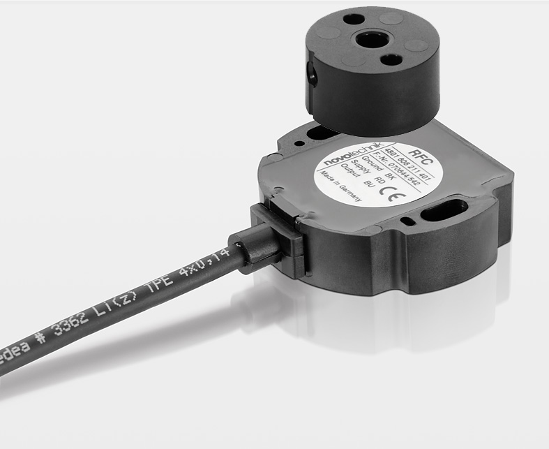
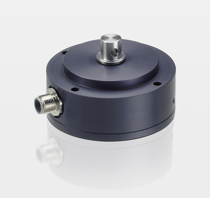
RFA4000
Touchless, compact and cost-effective NOVOHALL rotary sensor for small installation spaces. Selection of various analog and digital interfaces.
Range
Max. |
Output |
Protection
Min. |
Temp.
Min. |
Temp.
Max. |
Data sheet |
Remember |
| 360 |
Analog |
IP67 |
-40° C |
125° C |
|
|
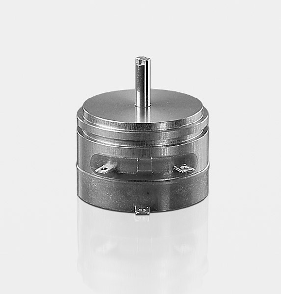
P2200
High-precision potentiometric low-torque rotary sensor, synchro housing 11
Range
Max. |
Output |
Protection
Min. |
Temp.
Min. |
Temp.
Max. |
Data sheet |
Remember |
| 345 |
Analog |
IP50 |
-40° C |
100° C |
|
|
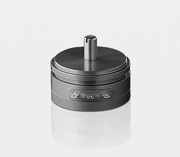
P2500
High-precision potentiometric rotary sensor, synchro housing 11
Range
Max. |
Output |
Protection
Min. |
Temp.
Min. |
Temp.
Max. |
Data sheet |
Remember |
| 345 |
Analog |
IP40 |
-40° C |
100° C |
|
|
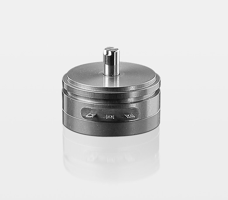
P4500
High-precision potentiometric rotary sensor, synchro housing 15
Range
Max. |
Output |
Protection
Min. |
Temp.
Min. |
Temp.
Max. |
Data sheet |
Remember |
| 350 |
Analog |
IP40 |
-40° C |
100° C |
|
|
P6500
High-precision potentiometric rotary sensor, synchro housing 20
Range
Max. |
Output |
Protection
Min. |
Temp.
Min. |
Temp.
Max. |
Data sheet |
Remember |
| 355 |
Analog |
IP40 |
-40° C |
100° C |
|
|
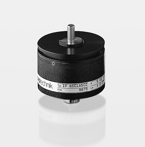
IP6000
High-precision potentiometric rotary sensor. Robust and sealed design
Range
Max. |
Output |
Protection
Min. |
Temp.
Min. |
Temp.
Max. |
Data sheet |
Remember |
| 355 |
Analog |
IP65 |
-40° C |
100° C |
|
|
IPE6000
High-precision potentiometric rotary sensor. Robust and sealed design with current interface
Range
Max. |
Output |
Protection
Min. |
Temp.
Min. |
Temp.
Max. |
Data sheet |
Remember |
| 345 |
Analog |
IP65 |
-25° C |
70° C |
|
|
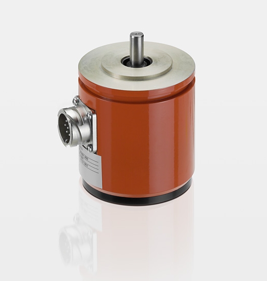
IPS6000
Precise potentiometric rotary sensor. Robust design for use in harsh operating conditions
Range
Max. |
Output |
Protection
Min. |
Temp.
Min. |
Temp.
Max. |
Data sheet |
Remember |
| 355 |
Analog |
IP67 |
-40° C |
100° C |
|
|
IPX7900
High-precision potentiometric rotary sensor for use in harsh operating conditions. Extremely robust, sealed and corrosion resistant.
Range
Max. |
Output |
Protection
Min. |
Temp.
Min. |
Temp.
Max. |
Data sheet |
Remember |
| 350 |
Analog |
IP67
IP69K |
-40° C |
120° C |
|
|
AW360
High-precision rotary sensor in robust design, with gap-free output voltage across full 360 °
Range
Max. |
Output |
Protection
Min. |
Temp.
Min. |
Temp.
Max. |
Data sheet |
Remember |
| 360 |
Analog |
IP65 |
0° C |
70° C |
|
|
AWS360
High-precision rotary sensor in robust design for use in harsh operating conditions. Continuous output voltage over a full 360 °
Range
Max. |
Output |
Protection
Min. |
Temp.
Min. |
Temp.
Max. |
Data sheet |
Remember |
| 360 |
Analog |
IP65 |
0° C |
70° C |
|
|
GP
High-precision potentiometric rotary sensor with reduction gear
Range
Max. |
Output |
Protection
Min. |
Temp.
Min. |
Temp.
Max. |
Data sheet |
Remember |
| 3845 |
Analog |
IP40 |
-40° C |
100° C |
|
|
IGP
High-precision potentiometric rotary sensor in robust design for use in harsh operating conditions, with reduction gear
Range
Max. |
Output |
Protection
Min. |
Temp.
Min. |
Temp.
Max. |
Data sheet |
Remember |
| 3845 |
Analog |
IP67 |
-40° C |
100° C |
|
|
SP1600
Very cost-effective and compact potentiometric rotary sensor with integrated connector and return spring
Range
Max. |
Output |
Protection
Min. |
Temp.
Min. |
Temp.
Max. |
Data sheet |
Remember |
| 125 |
Analog |
IP67 |
-30° C |
120° C |
|
|
SP2500
Precise, compact and inexpensive potentiometric rotary sensor. Simple installation and adjustment
Range
Max. |
Output |
Protection
Min. |
Temp.
Min. |
Temp.
Max. |
Data sheet |
Remember |
| 335 |
Analog |
IP40 |
-40° C |
85° C |
|
|
SP2800
Compact and robust potentiometric rotary sensor for use in various applications. Simple installation and adjustment
Range
Max. |
Output |
Protection
Min. |
Temp.
Min. |
Temp.
Max. |
Data sheet |
Remember |
| 345 |
Analog |
IP54 |
-40° C |
120° C |
|
|
SP4000
Cost-effective and compact potentiometric rotary sensor with integrated plug and return spring
Range
Max. |
Output |
Protection
Min. |
Temp.
Min. |
Temp.
Max. |
Data sheet |
Remember |
| 108 |
Analog |
IP69K |
-40° C |
125° C |
|
|
SP5000
Very cost-effective potentiometric rotary sensor with integrated plug
Range
Max. |
Output |
Protection
Min. |
Temp.
Min. |
Temp.
Max. |
Data sheet |
Remember |
| 120 |
Analog |
IP67 |
-40° C |
125° C |
|
|
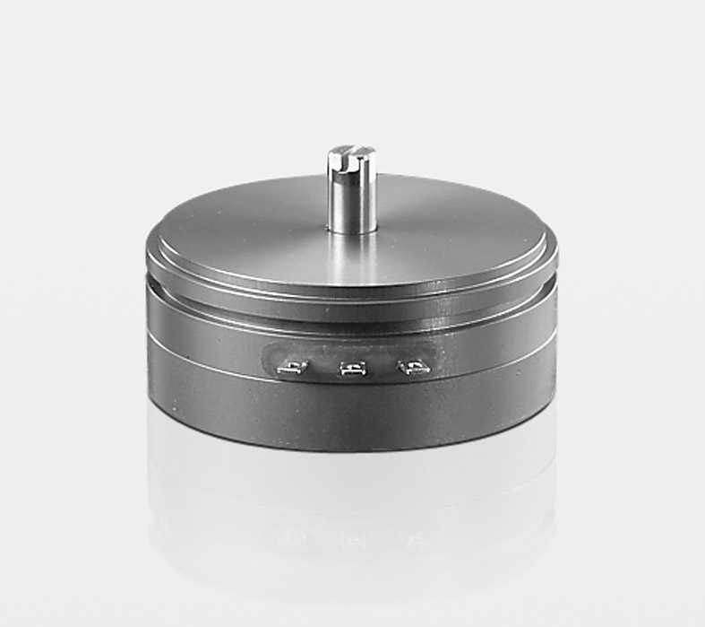
PRS
Resistance element / wiper combination with high accuracy. Suitable for flat installation spaces. Customized versions possible on request.
Range
Max. |
Output |
Protection
Min. |
Temp.
Min. |
Temp.
Max. |
Data sheet |
Remember |
| 355 |
|
IP00 |
-40° C |
100° C |
|
|
|
| Positions Tranducers |
|
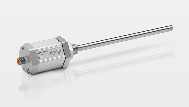
TIM with plug-in flange
Absolute rod style position transducer for integration in cylinders especially for mobile applications ; NOVOSTRICTIVE non-contacting, magnetostrictive measurement principle; non-contact position detection with ring position marker; unlimited mechanical life span
Range
Max. |
Output |
Protection
Min. |
Temp.
Min. |
Temp.
Max. |
Data sheet |
Remember |
| 2500 mm |
Analog |
IP67
IP69K |
-40° C |
105° C |
|
|
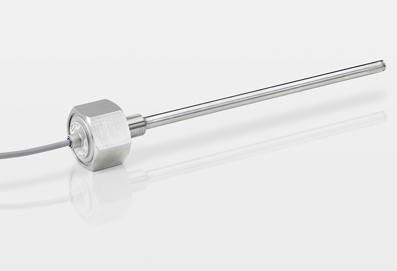
TIM with screw flange
Absolute rod style position transducer for integration in cylinders especially for mobile applications ; NOVOSTRICTIVE non-contacting, magnetostrictive measurement principle; non-contact position detection with ring position marker; unlimited mechanical life span
Range
Max. |
Output |
Protection
Min. |
Temp.
Min. |
Temp.
Max. |
Data sheet |
Remember |
| 2500 mm |
Analog |
IP67 |
-40° C |
105° C |
|
|
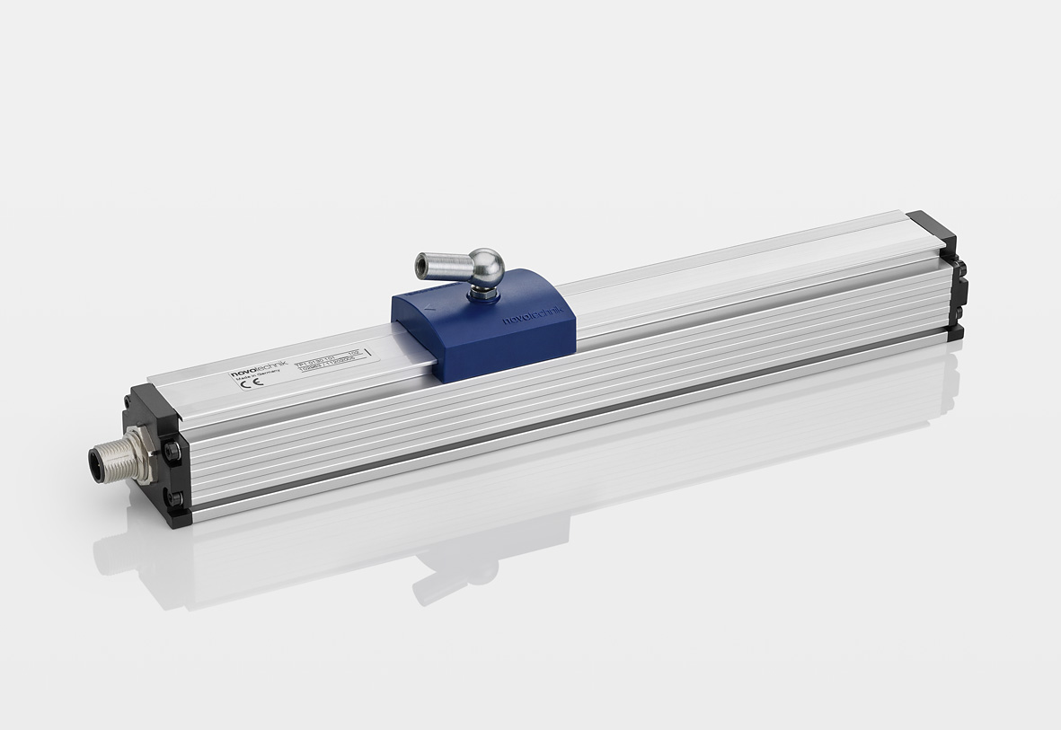
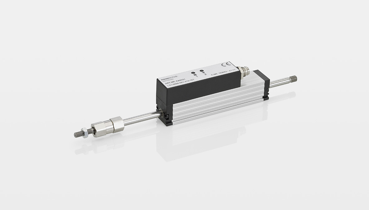
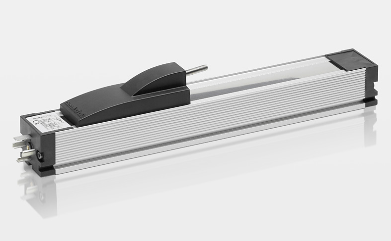
LS1 Transducer
Absolute transducer in compact profile design with double-sided supported actuating rod; NOVOPAD non-contating, inductive measurement principle; Teach-in function with status LEDs; ball coupling for backlash- and shear force free operation , long life span
Range
Max. |
Output |
Protection
Min. |
Temp.
Min. |
Temp.
Max. |
Data sheet |
Remember |
| 200 mm |
Analog |
IP40 |
-40° C |
100° C |
|
|
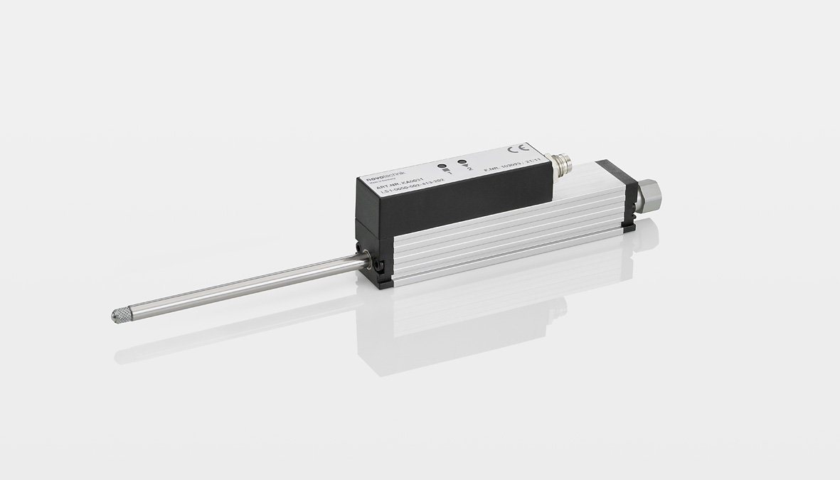
LS1 Transducer with return spring
Absolute transducer in compact profile design with double-sided supported actuating rod and internal return spring; NOVOPAD non-contacting, inductive measuring principle, Teach-in function with status LEDs, probe tip with pressed-in hardened metal ball, long life span
Range
Max. |
Output |
Protection
Min. |
Temp.
Min. |
Temp.
Max. |
Data sheet |
Remember |
| 100 mm |
Analog |
IP40 |
-40° C |
100° C |
|
|
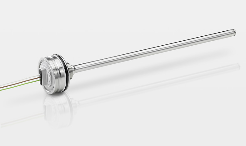
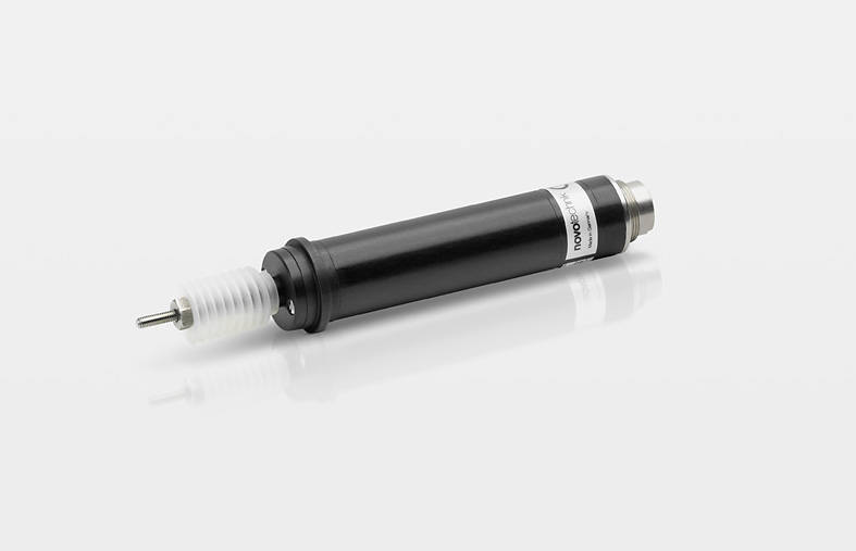
FTI
Absolute precision transducer with central mounting, durable because contactless measurement; completely encapsulated by a robust housing, temperature-resistant precision due to supplementary regulation winding
Range
Max. |
Output |
Protection
Min. |
Temp.
Min. |
Temp.
Max. |
Data sheet |
Remember |
| 10 mm |
Analog |
IP50
IP67 |
-25° C |
70° C |
|
|
F200
Inductive transducer with centering collar, integrated sealed hybrid electronic, DC power supply; floating DC voltage output, good temperature stability, maintenance-free plastic plain bearings and bellows; long long life
Range
Max. |
Output |
Protection
Min. |
Temp.
Min. |
Temp.
Max. |
Data sheet |
Remember |
| 20 mm |
Analog |
IP67 |
-30° C |
70° C |
|
|
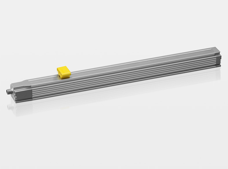
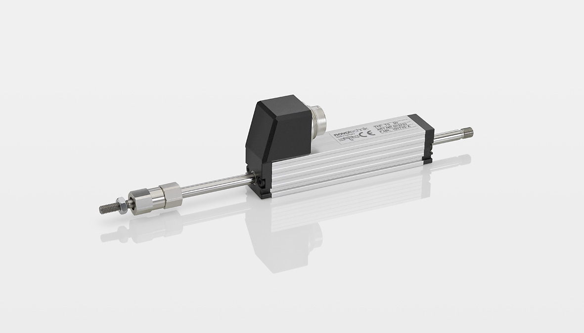
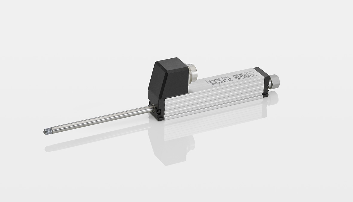
T / TS Transducer
Potentiometric position transducer in compact profile design with double-sided supported actuating rod; very high repeatability and adjustement speed; ball coupling for backlash- and shear force free operation , long life span
Range
Max. |
Output |
Protection
Min. |
Temp.
Min. |
Temp.
Max. |
Data sheet |
Remember |
| 150 mm |
Analog |
IP40 |
-30° C |
100° C |
|
|
TR / TRS Transducer with return spring
Potentiometric position transducer in compact profile design with double-sided supported actuating rod and internal return spring; very high repeatability and adjustement speed; probe tip with pressed-in hardened metal ball, long life span
Range
Max. |
Output |
Protection
Min. |
Temp.
Min. |
Temp.
Max. |
Data sheet |
Remember |
| 100 mm |
Analog |
IP40 |
-30° C |
100° C |
|
|
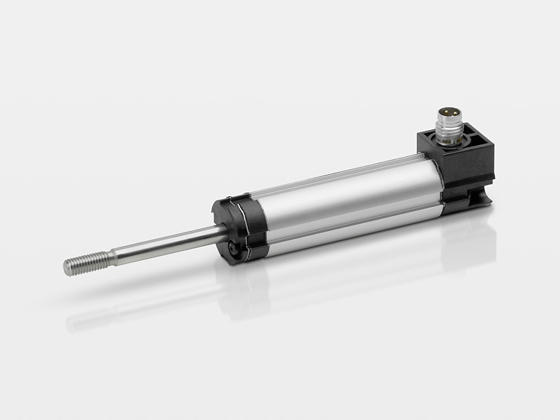
TEX pivot head mounting
Potentiometric position transducer in compact design with one-sided actuating rod; long life span and high adjustement speed; easy to assemble via low-backlash pivot heads with a large angle of freedom
Range
Max. |
Output |
Protection
Min. |
Temp.
Min. |
Temp.
Max. |
Data sheet |
Remember |
| 300 mm |
Analog |
IP54 |
-40° C |
85° C |
|
|
TEX Transducer with actuating rod
Potentiometric position transducer in compact design with one-sided actuating rod; long life span and high adjustement speed; Flexible mounting via clamps, bushing mounts or flange plates
Range
Max. |
Output |
Protection
Min. |
Temp.
Min. |
Temp.
Max. |
Data sheet |
Remember |
| 300 mm |
Analog |
IP54 |
-40° C |
85° C |
|
|
TEX Transducer with return spring
Potentiometric position transducer in compact design with one-sided actuating rod and return spring; long life span and high adjustement speed; Flexible mounting via clamps, bushing mount or flange plates; probe tip with pressed-in hardened metal ball
Range
Max. |
Output |
Protection
Min. |
Temp.
Min. |
Temp.
Max. |
Data sheet |
Remember |
| 200 mm |
Analog |
IP54 |
-40° C |
85° C |
|
|
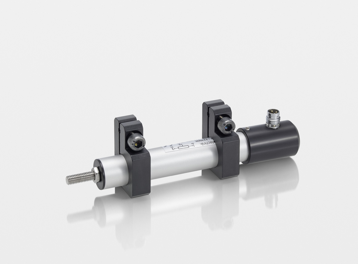
TX2 pivot head mounting
Potentiometric position transducer with very compact dimensions; robust design with metal flanges; sintered bronze plain bearing; long life span and high adjustement speed; easy to assemble via low-backlash pivot heads with a large angle of freedom; High protection class
Range
Max. |
Output |
Protection
Min. |
Temp.
Min. |
Temp.
Max. |
Data sheet |
Remember |
| 300 mm |
Analog |
IP67 |
-40° C |
100° C |
|
|
TX2 with mounting clamp
Potentiometric position transducer with very compact dimensions; robust design with metal flanges; sintered bronze plain bearing; long life span and high adjustement speed; easy to assemble via sliding metal mounting clamps; High protection class
Range
Max. |
Output |
Protection
Min. |
Temp.
Min. |
Temp.
Max. |
Data sheet |
Remember |
| 300 mm |
Analog |
IP67 |
-40° C |
100° C |
|
|
LWG
Potentiometric position transducer with double supported actuating rod; long life span and high adjustement speed; decoupled wiper tap; easy to assemble via low-backlash pivot heads with a large angle of freedom; High protection class
Range
Max. |
Output |
Protection
Min. |
Temp.
Min. |
Temp.
Max. |
Data sheet |
Remember |
| 750 mm |
Analog |
IP65 |
-30° C |
100° C |
|
|
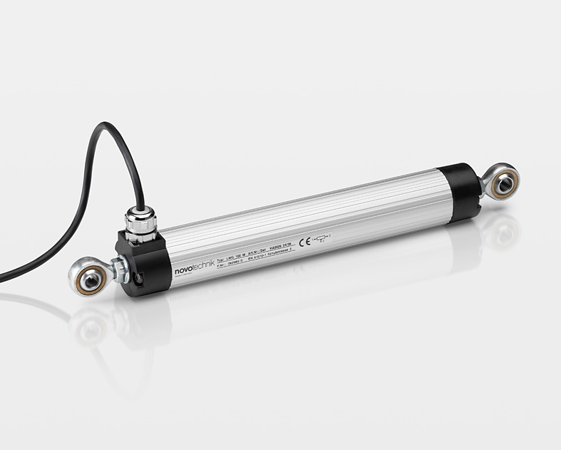
LWX-001
Potentiometric position transducer; robust design with metal flanges and patented pressure equalization system; long life span and high adjustement speed; easy to assemble via low-backlash pivot heads with a large angle of freedom; High protection class
Range
Max. |
Output |
Protection
Min. |
Temp.
Min. |
Temp.
Max. |
Data sheet |
Remember |
| 750 mm |
Analog |
IP67 |
-30° C |
100° C |
|
|
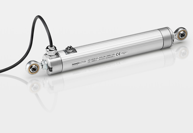
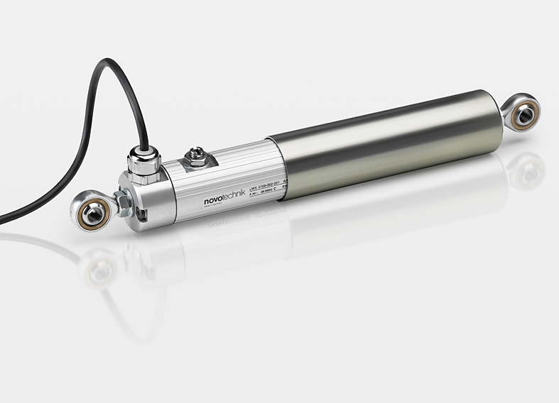
LWX-002, shaft protected
Potentiometric position transducer; robust design with metal flanges, patented pressure equalization system and an additional guard tube for the actuating rod; long life span and high adjustement speed; easy to assemble via low-backlash pivot heads with a large angle of freedom; High protection class
Range
Max. |
Output |
Protection
Min. |
Temp.
Min. |
Temp.
Max. |
Data sheet |
Remember |
| 750 mm |
Analog |
IP67 |
-30° C |
100° C |
|
|
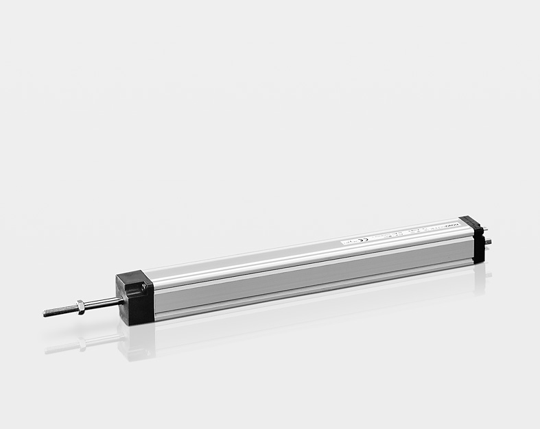
LWH
Potentiometric position transducer; pendular fixed slide bearing and decoupled wiper tap for stick-slip-free movement; long life span and high adjustement speed; easy to assemble via snap in and all side mountable clamps
Range
Max. |
Output |
Protection
Min. |
Temp.
Min. |
Temp.
Max. |
Data sheet |
Remember |
| 900 mm |
Analog |
IP55 |
-30° C |
100° C |
|
|
TLH
Potentiometric position transducer without actuating rod with lengthwise coupling for reduced overall dimensions; metal wiper carrier; shear force free linkage via ball coupling; long life span
Range
Max. |
Output |
Protection
Min. |
Temp.
Min. |
Temp.
Max. |
Data sheet |
Remember |
| 3000 mm |
Analog |
IP40
IP54 |
-30° C |
100° C |
|
|
PTP
Potentiometric position transducer in cost-optimized compact design; open housing for mounting in closed devices; variable mechanical customer interface; basic version for customized solutions
Range
Max. |
Output |
Protection
Min. |
Temp.
Min. |
Temp.
Max. |
Data sheet |
Remember |
| 300 mm |
Analog |
IP00 |
-40° C |
100° C |
|
|
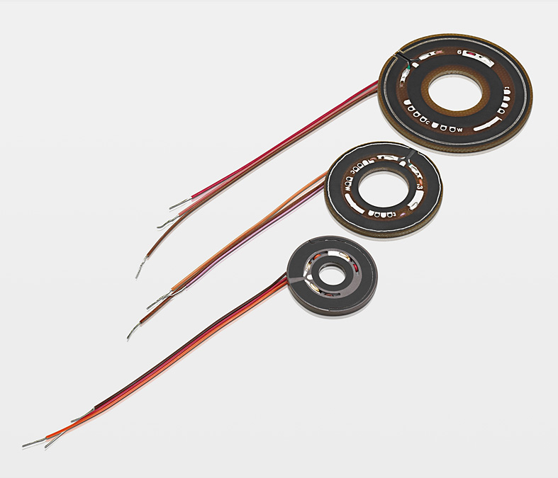
PTN
Potentiometric resistance elements and wiper; for mounting in closed devices; customized solutions with laser-linearization, switch function and redundancy technically feasible
Range
Max. |
Output |
Protection
Min. |
Temp.
Min. |
Temp.
Max. |
Data sheet |
Remember |
| 250 mm |
Analog |
IP00 |
-40° C |
100° C |
|
|
PTX
Potentiometric resistance elements and wiper; for mounting in closed devices; customized solutions with laser-linearization, switch function and redundancy technically feasible
Range
Max. |
Output |
Protection
Min. |
Temp.
Min. |
Temp.
Max. |
Data sheet |
Remember |
| 300 mm |
Analog |
IP00 |
-40° C |
100° C |
|
|
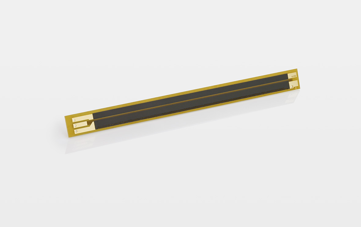
LFP
Potentiometric resistive elements with foil collector and mechanical pressure pin. Hermetically bonded structure. Handling is very simple since the sensitive potentiometer track is protected by the cover sheet.
Range
Max. |
Output |
Protection
Min. |
Temp.
Min. |
Temp.
Max. |
Data sheet |
Remember |
| 500 mm |
Analog |
IP67 |
-40° C |
125° C |
|
|
|
| Automotive And Customized Products |
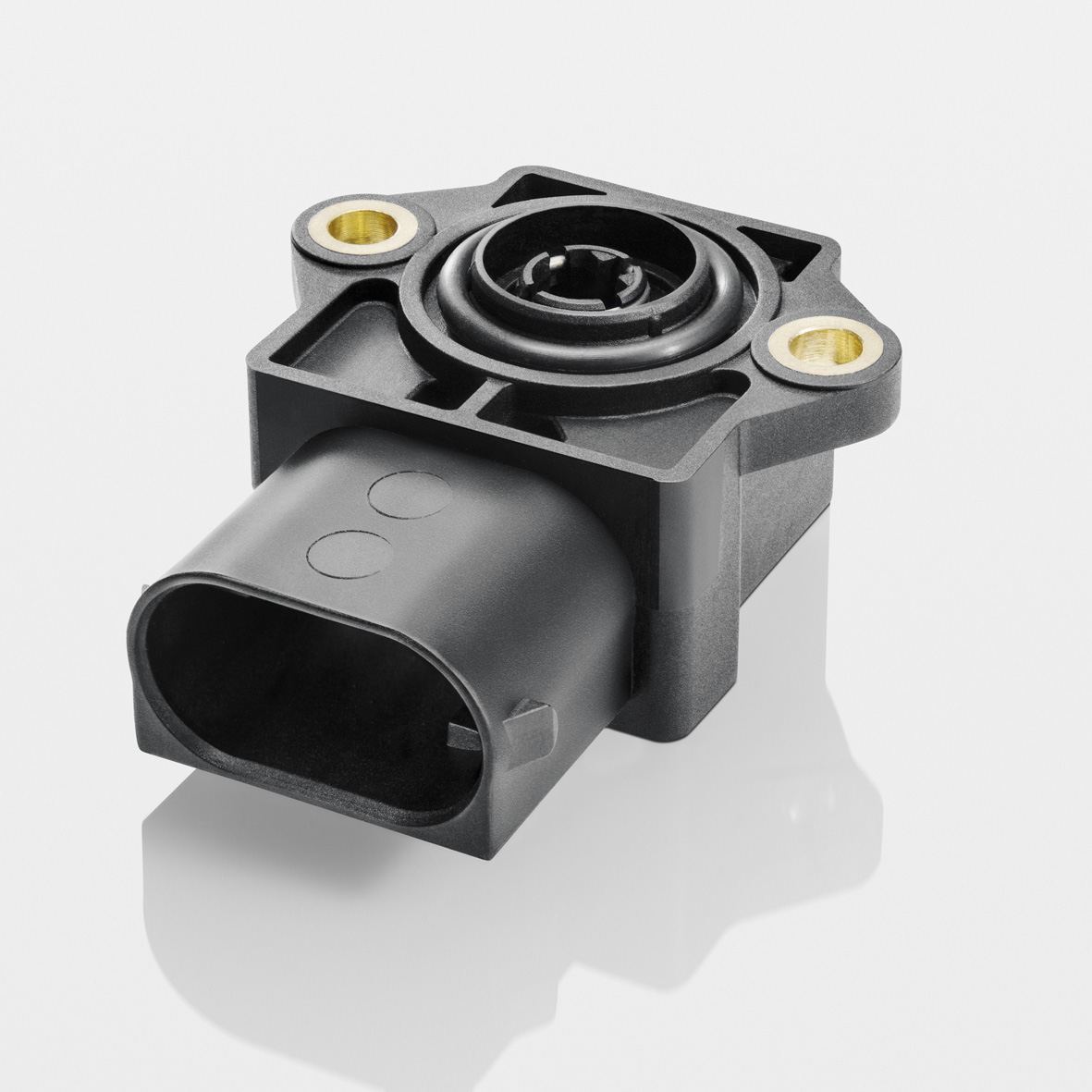
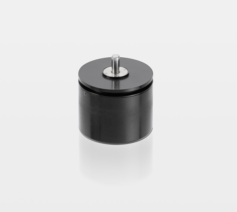
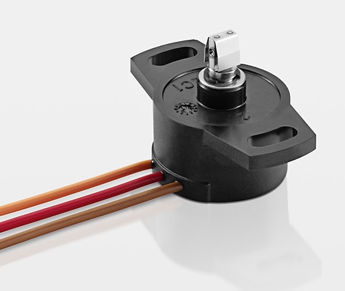
Steering angle Sensor
-
-
Application: Driving dynamics
The steering-angle sensor basically consists of a non-contact angle-measuring device or resistive tracks and wipers. The sensor, which is designed a a hollow shaft, is normally mounted on the steering column or at the steering gear.
Today adaptive control systems
-
contribute significantly to increasing driving safety in motor vehicles. These types of control systems improve the transversal dynamic behavior and assist the driver in critical steering maneuvers, e.g. when veering quickly or passing.
For more information please contact:
automotive@novotechnik.de,
+49 711 4489-222
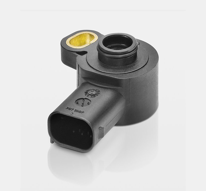
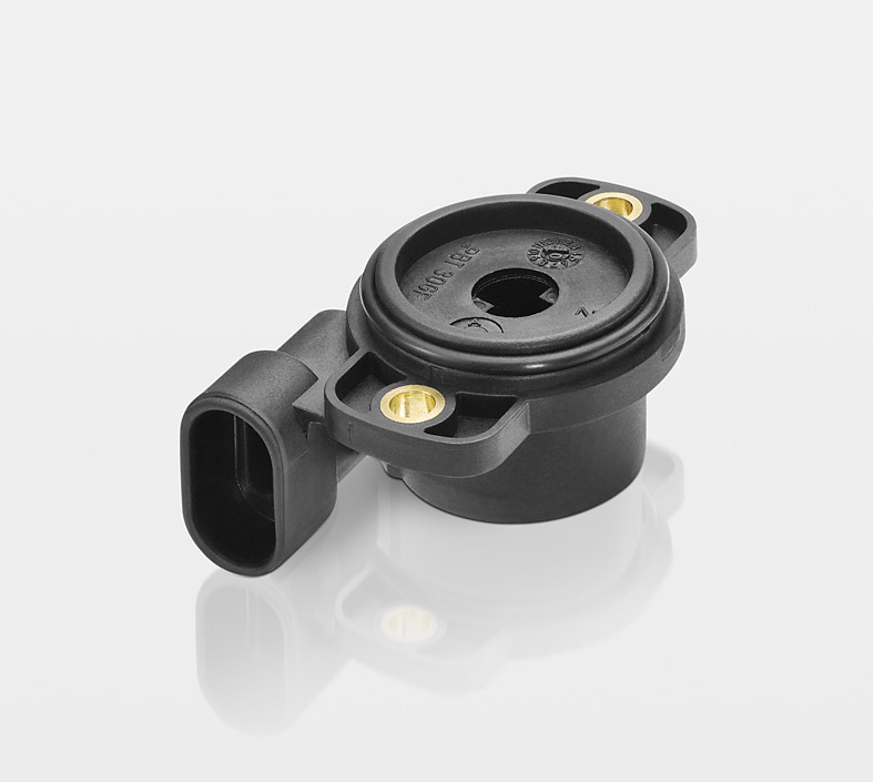
Electronic pedal Sensor
-
-
Application: Motor management
Electronic pedal sensor modules comprise an accelerator pedal, angle sensor and mechanics for simulating the traditional feeling of the accelerator pedal for the driver.
When the accelerator pedal is pressed
-
down, the pedal sensor transmits the information to the control electronics. Based on this information, the position of the throttle valve is calculated.
For more information please contact:
automotive@novotechnik.de,
+49 711 4489-222
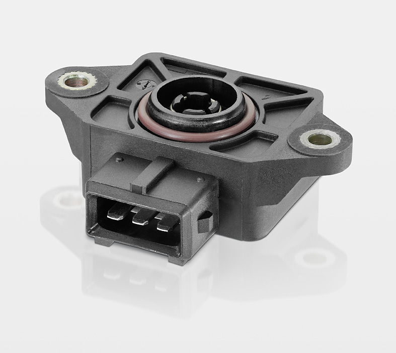
Throttling device E-Gas, Throttling device for idle speed control
-
-
Application: E-gas, idle speed control
The information detected from the pedal sensor are transmitted to the electric motor-driven throttle valve positionier via control and correction electronics. The current throttle valve position is measured by an integrated or adapted angle sensor.
The idle controller regulates
-
independent of the load the idling speed or the engine through the throttle position. This leads to an optimised fuel consumption.
For more information please contact:
automotive@novotechnik.de,
+49 711 4489-222
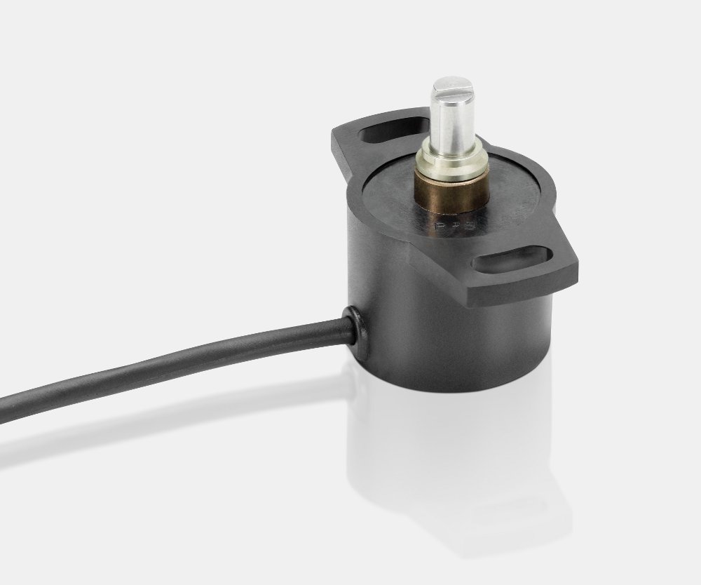
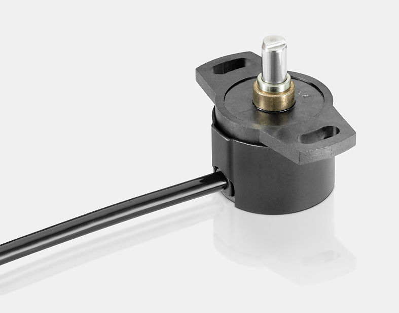
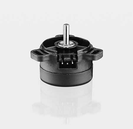
Angle sensor SP1600
-
-
A very cost effective and compactpotentiometric angle sensor with integrated power and reset spring.
-
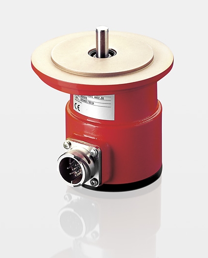
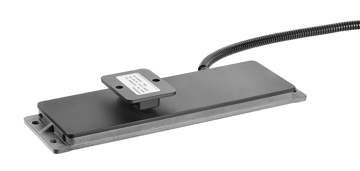
Absolute position transducer for steering cylinders
-
-
Application: Actual valve detection on hydraulic steerning cylinders
Robust customized sensor, NOVOPADnon-contacting inductive measuringprinciple.
- magnetic field resistant
- redundant for safety categerory 3
-
- non-contacting position detecting
- protection class up to IP 69K
For more information please contact:
linear@novotechnik.de,
+49 711 4489-197
|
| Signal Processing |
-
-
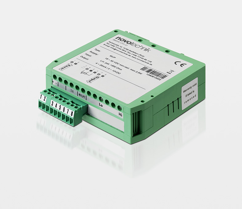
Signal Conditioners MUP 110 / MUP 160
for potentiometric sensors. Adjustable zero and span. Available with or without electrical isolation. Compact size.
-
-
Signal Conditioner MUP400
for potentiometric sensors. Simple teach-in function to adapt start and end point.Switchable current or voltage output.
-
-
Signal Conditioners MUP 080
for potentiometric sensors. Basic version with fixed voltage or current output, output range.
-
-
Signal Conditioners MUP 100/150
for position sensors series F200, AW360 and AWS360. Zero point and span adjustable, additional supply +/- 15 V for connected sensors.
-
-
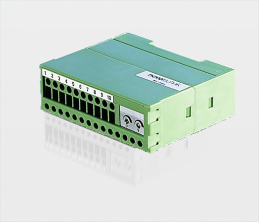
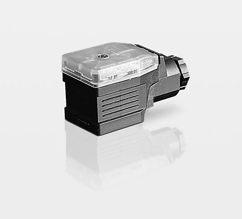
Signal Conditioners MUW
for position transducers series LWH und TLH. Electronics integrated inside the connector housing. Zero point and span optionally adjustable or fixed.
-
-
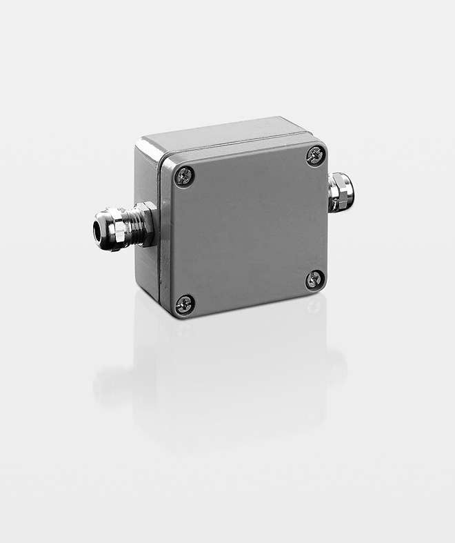
Signal Conditioners MUK 350
for potentiometric sensors. Electronics inside robust housing even for outside use. Zero point and span adjustable.

-
-
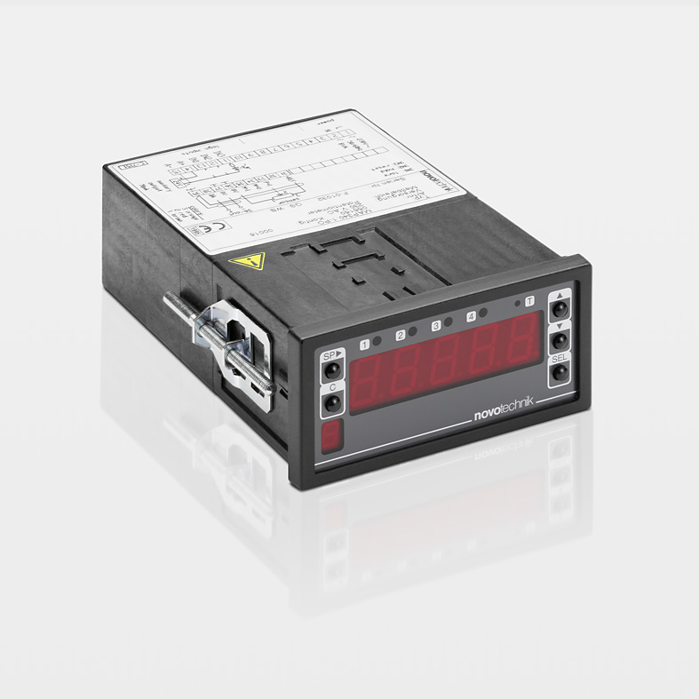
Multifunctional Displays MAP 300 / 400
for potentiometric and other sensors with analog interface. Highly accurate, displayup to 4 1/2-digits. Programmable mode, scaling, limit value, zero point and tare.Selectable analog and digital interfaces.
für potentiometrische Sensoren. Hochgenau, Anzeige bis 4 1/2-stellig. Programmierbare Betriebsart, Skalierung, Grenzwerte, Nullpunkt und Tarierwert. Wahlweise analoge und digitale Schnittstellen.
-
-
Multifunction Displays MAP 4000
for potentiometric and other sensors with analog interface. Cost effective, various programming possibilities, (input dimension, scaling, limit values, zero point, tare etc.). Selectable analog and digital Interfaces.
Useable also as data logger due to internal data recording ability.
-
-
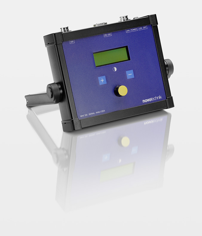
Measuring and Display Devices MAX 100
for contactless linear transducers. Supported interfaces: SSI 24, SSI 25, SSI 48 (DyMoS), Start/Stop. Binary and Gray Code, one button operation, RS232 interface, Display languages german and english.
|
| Sensor Technologies |
Even Without Power You can count on it…
-
How To Substantially Reduce Encoder Cost While Gaining Functionality With Multi-Turn Rotary Position Sensors.
Many applications require rotation counters that can measure angles greater than 360º. However the low-cost 10-turn potentiometers most design engineers are familiar with can’t always meet user requirements for resolution and reliability. As an alternative, optical absolute encoders are too expensive for many applications. These solutions require a continuous power supply or they will lose count when power is restored. Also, geared
-
technology/rotation counters are subject to significant wear. Novotechnik’s new 2800 Series multi-turn rotary sensors address this unfilled customer need. These are the the first rotation counters to be based on Novotechnik’s patented NOVOTURN™ technology – built on an enhanced giant magnetic resistance effect. They provide substantial cost savings compared to optical encoders, maintain reliability and accuracy, plus they offer additional useful features.
-
|
Potentiometers - Technical Definitions
1. Introduction
-
Rapid developments in the fields of control engineering and in microprocessor and semiconductor technology have resulted in the widespread use of electronically controlled systems in every branch of industry today. This has created a need for sensors that are inexpensive but, at the same time, sufficiently robust, both electrically and mechanically, to withstand a wide range of temperatures (e.g. from -40 to +160 degrees centigrade), particularly in applications involving large quantities, such as the automobile industry. Fig. 1 provides a summary of the various types of sensors for angular and linear motion
-
that are in use today. This paper is concerned with quality criteria (1) and (2) applicable to conductive-plastic potentiometers for use as sensors for angular and linear motion. Such potentiometers essentially comprise the following components:
1. The resistance element (support material + a resistance track of conductive plastic)
2. A wiper (precious metal alloy)
3. A drive shaft or acutating rod
4. Bearings (ball bearing or plain bearing)
5. Housing
-

Fig. 1
To top
2. Terminology / Terms and Definitions
-
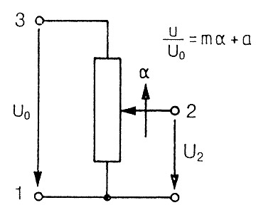
When we refer nowadays to a potentiometer as a sensor, it is important to bear in mind the statements made here only apply if the potentiometer is connected as voltage divider rather than as a variable resistor (rheostat) (Fig. 2). The wiper voltage must be connected, free of load, to an operational amplifier such as a 741, OP 07 or some other component with a high input impedance. Fig. 3 explains the
-
terms used, such as electrical and mechanical travel. L1 indicates the defined electrical travel. L2 indicates the continuity travel which also includes the non-linear connection fields Fig. 4. L3 indicates the total electrical contact travel of the potentiometer. L4 indicates the mechanical travel. An electrical potential need not be defined for the whole of this travel.
-
To top
3. Linearity/Conformity
-
Of all the quality features mentioned, linearity and conformity are the values most often defined in the existing literature (2). These terms express the extent to which the voltage output from a potentionmeter, and also other types of angular of linear movement sensor, differs from a prescribed theoretical function. In by far the majority of cases, the desired output function is directly proportional to the angel or linear movement that is input.
-
Formula: Fig. 5.
Whereby m characterizes the gradient, the offset voltage of the potentiometer and the linear or angular travel. Where there is a linear relationship, deviation is referred to as linearity. Where the relationship is nonlinear.
U = f (x) + a + b
the deviation is referred to as conformity.
-

Fig. 5
To top
3.1 Independent linearity
-
If a voltage U0 is applied to a potentiometer with a linear characteristic as in Fig. 5 and the wiper is moved in direction Alpha (standardized movement, angle 0;1 ) then the relationship illustrated in Fig. 6 will exist between the output voltage and the mechanically input value. The maximum deviation of the potentiometer curve from an ideal straight line is referred to as the independent linearity error. The slope and axis intercept of this straight line can be so chosen that the error f within the travel L1 is minimized. The error ±f is
-
indicated as a deviation in percentage terms of the output voltage from the theoretical in relation to the input voltage. Since direct measurement of the potentiometer characteristic does not make it possible to assess the extent of such an error, only the difference between the potentiometer characteristic and that of an essentially perfect master potentiometer is plotted as in the practical example given in Fig. 7. Typical values for independent linearity nowadays lie between 0.2 % and 0.02 %.
-

Fig. 6

Fig. 7
To top
3.2 Absolute linearity
-
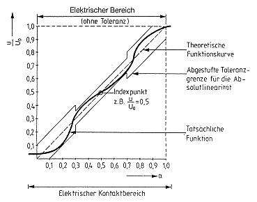
With the ever increasing automation of assembly lines, users are finding that values for absolute linearity are steadily gaining importance. Unlike independent linearity, for absolute linearity the reference slope is fully defined (Fig. 8) so that there is no need for subsequent system trimming. The definition of an index point establishes a relationship between the mechanical input value (travel or angle) and the output voltage.
-
Potentiometers whose linearity is defined by these criteria can be installed without a need for subsequent adjustment. As with independent linearity, it is best to determine the absolute linearity of a potentiometer by comparing its output with that of a master potentiometer. With absolute linearity, it is frequently necessary for the tolerance fields to be stepped. Fig. 9 shows a practical example.
-

Fig. 8

Fig. 9
To top
3.3 Absolute conformity
-
As already indicated under Point 3, conformity is a more general concept than linearity. The definition of absolute conformity is similar to that of absolute linearity. It is essential for an index point to be defined. The functional
-
relationship can either be determined mathematically to be defined. The functional relationship can either be determined mathematically or by plotting a number of points to establish a curve with the aid of suitable interpolation. It is
-
also possible with a potentiometer to achieve steadily increasing or steadily decreasing functions such as logarithmic, exponential, sinusoidal or cosinal functions.
To top
4. Contact resistance
-
Contact resistance is the resistance between the wiper terminal and the wiper's immediate point of contact on the potentiometer's resistive track. As will be subsequently explained, this contact resistance affects all the important quality features of a potentiometer. Contact or transition resistance can be broken down into three components. The first component, describes the integral voltage drop between the current-carrying track and the contact surface. This component is largely dependent on technology factors and amounts to several hundred Ohm. The second component, the external
-
component, is far more difficult to master than the first. This external transition resistance has much in common with the contact resistances occurring in switches and plug- and socket-connectors. It is caused by the transition between the wiper and the potentiometer track not being ideal from an electrical viewpoint. Metal oxides, chlorides and sulphides, mixed with various organic substances, can result in the formation of thin nonconductive facings at the interface. If not kept within bounds, this external transition resistance can, under
-
unfavourable conditions, lead to complete failure to keep within a tolerance range. It is absolutely essential that the materials used in potentiometer manufacutre be subjected to stringent quality control and be matched one with another. The third component, the dynamic component, is related to dynamic drive forces acting on the wiper at high speeds of actuation. With the aid of damped wipers, actuation speeds of up to 10 m/sec can be achieved without any appreciable increase in the dynamic component of contact resistance.
To top
5. Linearity errors due to electrical circuitry
-
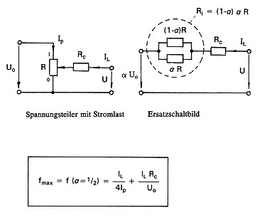
From here onwards, we are only concerned with the linear characteristics (linearity). Relationships must be suitably adapted for applications with non-linear characteristics (conformity) but there are no essential differences. As already mentioned in Section 2, the required linearity values can only be utilized so long as the signal output by the sensor "potentiometer" carries no current. We have now to consider the effect of wiper current on linearity. Fig. 10a illustrates the functional
-
relationship between wiper current, contact resistance and linearity error. As is shown by the example in Fig. 10b (Characteristic 4), with a wiper current of 10 µA and a contact resistance of 10 kOhm, a potentiometer which has a resistance of 2 kOhm already has linearity error of 1.1 %. A similar situation arises with an ohmic load. This clearly shows how important are the roles played by both wiper current and contact resistance.
-

Fig. 10a

Fig. 10b
To top
6. Linearity errors resulting from mechanical coupling
-
If there is axial misalignment (eccentricity) between the drive shaft and the shaft of a potentiometer used to sense angular, motion, this will cause a linearity error that increases as the coupling radius decreases in relation to the degree of eccentricity. The following equation determines the maximum relative error
-
Fmax = E/Pi · rk
where E = Eccentricity
und rk = the coupling radius.
It is only possible to take full advantage of the linearity or conformity of any rotationary sensor system, if
-
coupling alignment errors (offset and angular misalignment) are avoided or at least reduced to a mimimum. This means that with highly accurate measurement systems, due allowance must be made for any coupling misalingment in accordance with the above equation.
To top
7. Smoothness definitions
-
When, some 30 years ago conductive plastic potentiometers were first introduced onto the market, it was apparent that although the winding jumps which were a feature of wire-wound potentiometers had been overcome, absolute smoothness of the output voltage could not be achieved. Following some basic reserach by. h.
-
Wormser 4, 5, 6 , the term "smoothness" was included in the standard issued by the Variable Resistive Compontents Institute (VRCI). Although this definition was adequate at that time it cannot serve as a system definition for many applications. This is because it is now possible to produce potentiometers with
-
appreciably better smoothness and linearity values. For this reason, Novotechnik has sought over the past 15 years to develop definitions better suited to the current state fo the art. The various methods used are discussed and evalutated below.
To top
7.1 Smoothness
-
Smoothness is a measure of the deviations from perfect regularity that appear in the output voltage of a potentiometer. This irregularity is measured over a specified travel increment, for example 1 %, and is expressed as a percentage of the applied voltage. For the measurement of smoothness, the VRCI definition calls for a bandpass filter to be used as a means of suppressing any linearity error and for the potentiometer to be operated
-
with a load resistance (e.g. 100 . Rp). This method has certain disadvantages:
a) The use of a filter causes both the absolute wiper velocity and any changes in such velocity to affect the smoothness values. Since the filter partly integrates and partly differntiates, the chart-recorded smoothness curve does not accurately indicate the variations in the output signal.
b) The load applied to the potentiometer also contributes to error by causing
-
variation in the contact resistance which is greatest with the wiper at the voltage application end and lowest at the grounded end of the potentiometer track.
c) The use of a 1 % evaluation window is not accurate enough for many of today's applications.
d) The sometimes arbitrary selection of a filter type, load resistance and travel increment results in-smoothness values not being directly comparable.
To top
7.2 Microlinearity
-
In 1978, Novotechnik introduced the term Microlinearity, which is defined as the maximum linearity variation within a travel or angular increment that amounts - as with smoothness measurement - to 1 % of the electrical range if nothing to the contrary is defined. Microlinearity is indicated as a percentage of the absolute voltage that is applied. Fig. 11 illustrates the characteristic obtained for a potentiometer with a microlinearity error. This was evaluated by a computer-supported system while making linearity measurements. The travel increments
-
are super-imposed on the linearity curve and have an overlap of at least 50 %. Contrary to a smoothness measurement, the error here is pureley a linearity error that describes the maximum error within a defined increment. Microlinearity does not, however, make it possible to determine whether a potentiometer will be suitable for a particular applications because any variations in gradient (sensitivity) can only be determined with considerable difficult.
-

Fig. 11
To top
7.3 Relative gradient variation (RGV)
-
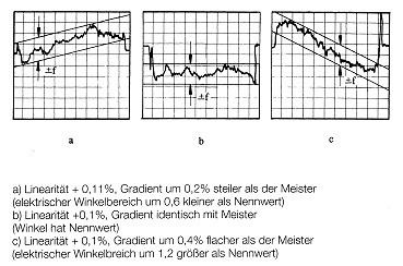
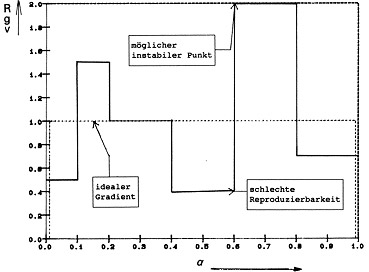
If, in a highly sensitive control system, the amplification should, for example, be so arranged that the control circuit will be stable with the mean slope (gradient) of the sensor, then it is important to be aware of any variations there may be in that slope (Fig. 12a, Fig. 12b). If, at any point, the gradient is appreciably steeper than the mean gradient, then there will be a higher closed-loop gain in this position and this could lead to feedback oscillation. If, on the other hand, the gradient is less steep at some point than the mean gradient, then repeatability would be reduced and there would be less control accuracy. If we relate this type of local gradient
-
variation gl to the mean gradient go of the potentiometer, then this criterion is independent of the potentiometer length and can be used for the direct comparision of various potentiometers.
|
RGV
|
|
local gradient
|
|
gl
|
|
=
|
—————————
|
=
|
—
|
| |
mean gradient
|
|
go
|
(Fig. 13)
The RGV is indicated as a ± deviation in percentage terms from L (standardized mean gradient).
-

Fig. 12a

Fig. 12b

Fig. 13
To top
7.4 Interpretation of RGV
-
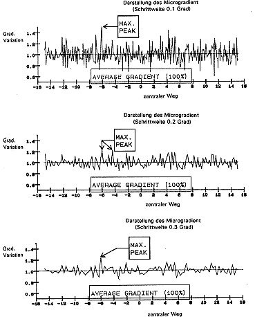
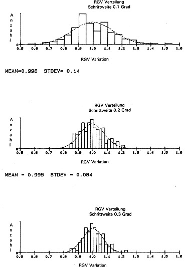
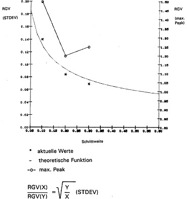
Measurements have shown that with conductive-plastic potentiometers, gradient fluctuations are statistically ditributed to travel increments of less than 1 µm, i.e. there is no periodicity or regularity. Fig. 14a shows the RGV curve and Fig. 14b the RGV values with step widths of 0.1, 0.2 and 0.3°. The form of these distributions more or less in conformity with the normal distribution to be expected in view of the central limit value principle. The mean distribution value is around 1 (mean gradient), the variance (STDEV) decreases as the step width increases. Since each individual RGV value represents a mean value, it is to be expected that the variance of such mean values will decrease with a root function in proportion to the increase in step size, since each such increase amounts to an increase in the size of the random sample.
-
|
RGV(X)
|
|
√
|
Y
|
|
|
————
|
=
|
—
|
applies for STDEV
|
|
RGV(Y)
|
|
X
|
|
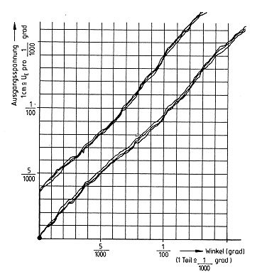
In Fig. 15 this variance has been plotted as a function of the step width. RGV variance can thus be considered as a characteristic quality feature of a potentiometer. The functional relationsship also serves to indicate the maximum resolution of a potentiometer which is not infinite, as many potentiometer manufacturers would imply. Maximum RGV values have also been plotted in Fig. 15. This curve, like the mimimum value curve, does not of course, obey statistical laws but arises from the inclusion of defective positions and faults in the system "potentiometer" as a whole. These values are vital criteria for assessing the stability and repeatability to be expected of a control system.
-

Fig. 14a

Fig. 14b

Fig. 15
To top
8.1 Resolution
-
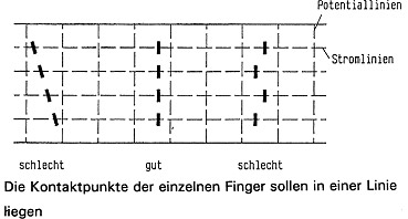
When measuring RGV values of potentiometers up to synchro size 20 from series production, with step widths of 0.1° RGV values of ± 10 % are obtained. If we specify the RGV value of ± 100 % as the resolution limit, from the equation in 7.4 we obtain with 10 % a
-
resolution of 1/1000°. The degree of resolution is primarily determined by the homogeneity and grain-size distribution in the conductive plastic layer, by the wiper contact surface running parallel to the equipotential lines (Fig. 16a, 16b) and by the wiper current.
-

Fig. 16a

Fig. 16b
To top
8.2 Hysteresis
-
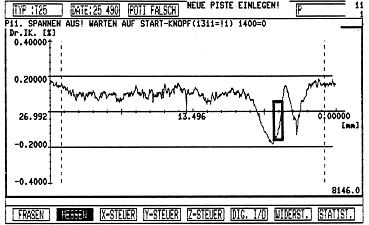
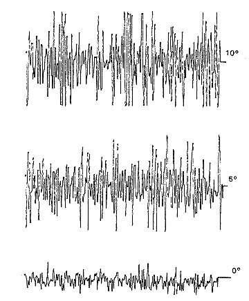
The hysteresis value specifies the signal differential resulting if a prescribed position is approached from one side, the point is travelled over and the same position approached from the other side. Hysteresis is mainly affected by mechanical factors such as the bearings, th stiffness of the wiper system and the coefficient of friction between the conductive layer and the wiper. For this reason, attention must be paid to ensure a backlash-free, rigid mechanical coupling. This can be achieved using, for example, a spring-borne concial pin or lever. Fig. 18 shows the recorded hysteresis of a
-
Novotechnik standard potentiometer. The measuements were taken with clockwise and counterclockwise rotation being repeated three times. While the curves recorded in one direction almost coincide (indicating goog resolution), in the opposite direction they indicate an hysteresis of around four thousands of a degree. The fact that the curves in one direction almost coincide and that there is an constant hystersis in the opposite direction indicates a stable displacement of the wiper contact line which means there is no stick-slip effect.
-

Fig. 18
To top
8.3 Repeatability
-
This term is generally replaced by reproducibility. By repeatability we mean any optional approach movement towards a prescribed position from the same direction.
-
-
To top
8.4 Reproducibility
-
This term is taken to mean any optional approach movement towards a prescribed position from various directions. It represents the sum of 2 x resolution + hyteresis.
-
-
To top
9. Temperature and humidity coefficients
-
In many data sheets issued by potentiometer manufacturers, reference is frequently made to the temperature coefficient (Tk) and humidity coefficient (Fk) of the nominal resistance. Where potentiometers are used as voltage dividers (Fig. 2), these values are irrelevant. For this application, it is the Tk and Fk applicable to the voltage divider behaviour which are of significance. It often also happens that the humidity is
-
not kept constant while making Tk measurements, with a result that a mixture of Tk and Fk is often given as a temperature coefficient. Detailed measurements made by Novotechnik have show that the Tk and Fk of the nominal resistance in conductive-plastic potentiometers (without housing) are of an order of magnitude somewhat less than 200 ppm/°C and 500 ppm/% RH respectively. The Tk and Fk of the
-
voltage-dividing behaviour are some two orders of magnitdue lower which means that here changes within a range of less than 5 ppm/°C and 5 ppm/% RH can be expected, ensuring constancy over a wide temperature and humidity range. However, this advantage can only be utilized given a suitably designed housing and if, for example, no trimming resistances are used in the potentiometer circuit.
To top
10. Service life
-
The magnitude of the contact resistance and the wear to which the resistance track is subjected and the resulting change in electrical characteristics dertermine the number of operations to which a potentiometer can be subjected and thus also its service life.
Although of considerable importance for industrial applications, no standard has so far been issued that specifies a service-life definition or a particular method of testing. It is, of course, most difficult to specify a value for wear or for an increase in contact resistance for a given number of actuation cycles since such values are markedly influenced by such external factors as temperature and humidity, and by mechanical and chemical influences.
Such values need to be established for each particular application. This applies to a lesser extent for the method of testing, and here the establishment of standard method would facilitate comparing the service life of various potentiometers. Unless the customer
-
specifies some different procedure, Novotechnik now uses two methods of testing. The first is a practical test in which extremely small wiper movements are simulated such as frequently occur in feedback control systems. Typical values are: Wiper travel 2° Test frequency 100 Hz.
This dither test permits a relatively rapid result to be obtained concerning contact reliability and any change in gradient within a micro range since, at such a high frequency, some 8.6 milion cycles can be effected daily. The second test, the half-stroke test, gives information concerning linearity changes, zero-point shift and wiper wear. This test is performed at a frequency of 10 Hz (0.86 million cycles per day) over 50 % of the track length. As is shown in Fig. 19, this results in a maximum linearity change. A criterion for rejection here might be a doubling of linearity in relation to the state when new and a maximum contact resistance value.
-

Fig. 19
|
Hall - / Magnetrostriction
Hall
-
When current flows through a Hall element, it supplies a voltage perpendicular to the current flow if a magnetic field acts vertically on both. As this voltage runs proportionally to the magnetic field strength, it is extremely simple to conduct a contact-free angular measurement by attaching a position magnet on a rotating shaft.
In the recent past this technology has made advances that make this sensor
-
ideal for exact angular measurement. By combining several sensor elements and integrating the entire signal processing system in a few components, complex systems are possible in an extremely small space.
The systems operate virtually insensitive to ageing and independently of field strength fluctuations of the sensor magnets.
Both contact-free, shaft-guided and
-
contact-free systems without a mechanical shaft connection enable measurement over up to a full 360° or even over several rotations.
High resolutions with excellent dynamics, broad mechanical tolerances and fast feasibility of special customer-specific solutions are additional convincing properties of this technology.
Magnetostriction
-
The elastic deformation of the molecular structure of ferromagnetic materials like iron, nickel, cobalt and their alloys is called magnetostriction. The micromechanical deformation takes place during a change in the magnetisation. The magnetic structure of ferromagnetic materials consists of the sum of countless small elementary magnets. The elementary magnets with the same magnetic orientation are grouped in limited areas called Weiss domains. The magnetic orientation of the Weiss
domains is arbitrary in the non-magnetised state. When exposed to an external magnetic field, a certain number of domains spontaneously
-
orient themselves in the direction of the magnetism. The number of domains that orient themselves in the direction of magnetisation is dependent both on the magnetic field strength of the external field and on the mechanical properties of the ferromagnetic material. The change in magnetisation of the domains produces a spontaneous change in the mechanical form, whereby a mechanical wave results. The mechanical wave is a torsion wave which results at the location of the excitation by the external magnetic field. The torsion wave is propagated in the ferromagnetic material at a speed of 2,800 m/s. This physical property is the basis for magnetostrictive position transducers.
-
A ferromagnetic material with a marked magnetostrictive property (waveguide) is positioned along the measuring path in a rugged housing. An external magnetic field (position transducer) marks the measuring position. The spontaneous change in magnetisation is triggered by the interaction of the external magnetic field and a very short current pulse, which flows through the waveguide. The torsion wave is propagated in the waveguide. The time between excitation and the reception of the torsion wave in a wave converter is converted to the corresponding position value in the electronics.
|
DyMoS – The interface for reliable communication at high transmission speed
Magnetostrictive transducer requirements for the interface:
-
- Interface with reliable transmission and high update rate for the position
-
Identification of the transducer system
-

Fig. 1
1. Features:
-
The Novotechnik DyMoS interface for magnetostrictive transducers is a uni-directional interface combining the data integrity of bus communication with the high transmission rate of the SSD interface. The speed at which the position values from the magnetostrictive transducer system are provided is adjusted to the transmission rate of the interface, thus achieving an overall update rate of output values to 16 kHz.
The data frame consists of 2 x 20 data bits. Formatting of the data frame is fixed in the transducer and can consist of 2 position values or one position value and the velocity value. An additional benefit of the Novotechnik interface is the time coordination of the transmitted position values with the internal
-
sequence of the measurement and the data preparation, with a continuous cycle of data querying. This ensures error-free calculation of the velocity and acceleration. The drivers are RS422/485 conformal. The transmission speed is from 25 Kbps to 1 (2) Mbps.The traceability and documentation of the transducers used in the application represents an additional advantage of the interface. This is accomplished using a system identification which the transducer sends at each power-up. The system identification consists of the part number (model and stroke length) and a unique number. The system information can also be used for unique assignment of the transducer within the application to prevent faults and damage caused by connecting the wrong transducer to the machine.
-
To top
2. Technical Description of the Interface
The communication frame consists of the 3-bit system frame, the 2 x 20-bit data frame, and the 5-bit CRC.
2.1 System Frame
-
The system frame consists of the funktion bit, the error bit and the system bit.
- Function Bit – is always High and indicates the start of transmission.
- Error Bit – is High-active. The function of the magnetostrictive transducer is monitored internally, both as a pure hardware function and by means of a plausibility check of the position values. Should an error occur, the error bit is set
-
High. On the receiving side the decision can be made at the start of transmission whether the received data are valid or not.
- System Bit – The system bit is used for defined recognition of the sent data. The system bit is Low when data (position value) are being sent and High when the transducer system identification is being sent.
-

Fig. 5
To top
2.2 Data Frame:
-
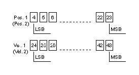
The data frame consists of 2 independent 20-bit frames. The data are formatted from LSB to MSB within the frames.
-
- Position value: 20 bits. The bit format is intended for a transducer having 5 m of stroke and a resolution of 5 µm.
- Velocity: 20 bits. The velocity resolution is 2.5 mm/s.
-
Fig. 6
To top
Transducer models:
-
Standard = The data frame consists of 2 independent 20-bit frames. The data within the frames are formatted from LSB to MSB.
-
Option = 2 Hardware interfaces: Interface 1: Position 1 and Velocity 1
-
Interface 2: Position 2 and Velocity 2. (Fig. 1).
2.3 CRC: Cyclic Redundancy Check
-
The CRC-Frame consists of 5 bits (Bit 44-48). For a 5-bit CRC the generator
-
polynomial has 6 places. The generator polynomial is defined as shown in Fig. 5
-
To top
3. System Identification
-
The uni-directional Novotechnik interface also implements transmission of the device identifier. Transmission of the identification data is automatic at each power-on. The identification data are sent in the first four transmission frames. After the system identification is
-
sent, the transducer automatically switches over to data (run) mode. The two transmission modes are differentiated using the system bit. When the identification is being sent, the system bit is High (=1), and when data are being sent the
-
system bit is Low
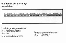
- Stroke length, 0500 for stroke length = 500 mm
- Serial No. YYCWCW1234.
To top
4.1 Communication
-
The Novotechnik interface offers the options of a 48 cycle mode or a continuous cycle. The 48 cycle mode conforms to SSI protocol. Data are sampled with the clock of the receiver and data is output synchronous with
-
positive edge of the clock. After the 48 data bits have been transmitted, a time tm of 10 µs follows during which the output is Low. After tm has elapsed, the output of the magnetostrictive transducer goes to High. With the clock
-
the current data, corresponding to the last update, are sent at 16 kHz. The sequence of the internal data update and data transmission is shown in Fig. 2.
To top
4.2 Continuous cycle mode
-
A simpler and more reliable solution is achieved by using continuous sampling mode (Fig. 3). The advantages of data transmission in this mode are:
- Precise timing of the data
- Easier handling of the clock generation
- The data are updated in the controller continuously at max. 16 kHz
- The controller has optimum access to the data.
-
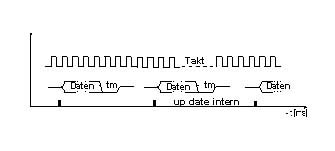
In continuous sampling mode the clock is always present on the transducer system. The transducer system starts data transmission following the internal update. After the 48 bits are sent, a time tm follows, during which the output is Low. The data can be stored in the controller in a dual port RAM, so that the controller’s CPU always has
-
access to the most current data. Even if the CPU does not access with absolutely precise time accuracy, it will still be ensured that the data can be allocated to a very accurate time sequence. This also allows the velocity to be calculated with high precision.The sequence of internal data refreshing and data transmission is shown in Fig. 3.
|
1. Synchronous Serial Interface (SSI)
-
The synchronous serial interface is a digital interface for absolute position and rotary measuring systems. It enables position and angular information to be transmitted digitally, absolutely and without bus overhead. As a result, it is especially well-suited for applications in which reliability and signal robustness are required in an industrial environment.
-
Transmission is synchronous to the request of the controller, and one bit of the position value to be output is transferred with each clock pulse. The clock/data signals are transferred differentially via an RS 422 interface. Data formats are binary or Gray-encoded with a 24 or 25-bit position resolution.
A parity bit for increased data security
-
can also be attached to the data format ("SSI26"). Possible clocking frequencies are in the range from 60 kHz to 2 MHz, and update rates of up to 16 kHz can be achieved.
The maximum achievable clocking frequency is dependent on the cable length and the driver blocks used.
This makes the SSI interface reliable, dynamic and inexpensive.
2. CANopen Interface
-
CANopen is an internationally standardized bus protocol based on the seven-layer ISO/OSI reference model. It
was developed by the CIA (CAN-in-Automation user and manufacturer association) and has been standardized as the European standard EN 50325-4 since the end of 2002. CANopen uses layer 1 and 2 of the CAN standard originally developed for use in cars (ISO 11898-2) as a transmission technology.
The bus system enables each device to
-
send messages (multimaster capability). Messages on the bus are received by each bus device (broadcast communication). Each bus device then decides whether or not these messages are processed based on its local intelligence.
A broad range of methods for setting the parameters of bus devices and for error detection
and treatment equip the CANopen protocol with out-standing properties.
-
With reference to positions sensors, all relevant device data of the higher-level controller can easily be imported via electronic data sheets (eds files). Thanks to the availability of features like cam switches, limit value switches, speed data etc., a true measured value for connected components is provided here.
CANopen is suitable for use as an interface in both dynamic applications and in complex control networks.
To top
3. Quadrature Interface
-
The quadrature interface was originally developed for incremental measuring systems.
Here the material measure is applied to a glass pane or strip. This is then scanned with optical systems. Two signals are generated, i.e. an A and a B pulse with a positive or negative phase offset of 90° respectively, depending on the direction of movement. The number of A or B pulses is a measure of the
-
distance covered, and the pulse width of the A/B pulses is therefore dependent on the speed of movement.
In addition, optical systems usually have a reference track, which only outputs a signal once along the entire measuring distance in order to reference the incrementally determined position. This is necessary to derive an absolute position from the A/B pulses which follow.
-
No reference traverse is necessary for absolute measuring position and rotary sensors as, for example, is the case with magnetostrictive position measuring systems.
A magnetostrictive position measuring system with a quadrature interface transfers the correct number of A/B pulses in accordance with the current absolute position on request.
To top
4. DyMoS Interface
-
Like the SSI interface, the DyMoS interface is based on the RS422 standard. With various additions, it combinesthe simplicity of synchronous serial transmission with the data transmission and diagnostic functions of bus interfaces.Here the data format is 48-bit, which is divided up as follows: the first three bits are system data,
-
followed by 40 data bits and 5 CRC bits. The 40 data bits can be formatted both as position and speed (for a position transducer) and as two position data(with 2 position transducers) with a resolution of 20 bits each. The system data can be used to monitor the state of the measuring sensor and the CRC bits for monitoring transmission. In addition
-
to the position data, information on the sensor (model and serial number) is output via the DyMoS interface following "Power On" so that the measuring sensor can be clearly assigned in the application.As with the SSI interface, the maximum transfer rate is 16 kHz.
|
|