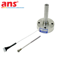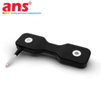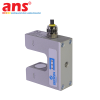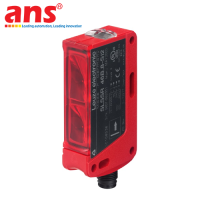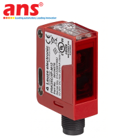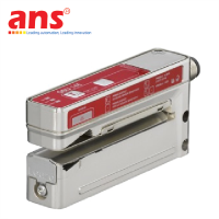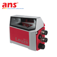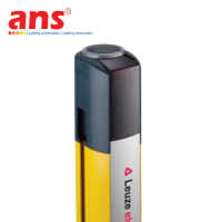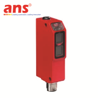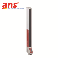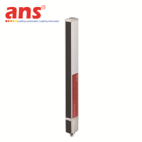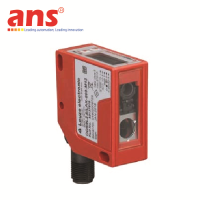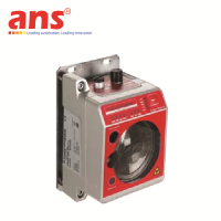
Leuze LE3C/4W-200-M8 Sub-miniature Throughbeam Photoelectric Sensor Receiver
Price: Contact
Brand: Leuze
Category: Cảm biến công nghiệp
Supplier: AnhNghiSon
Origin: Germany
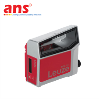
Leuze LE3C/4W-200-M8 (Order Code: 50147147)
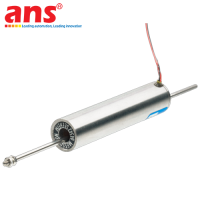
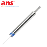
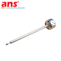
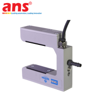
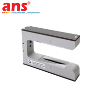
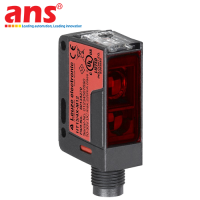
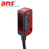
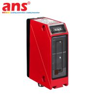
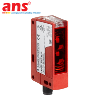
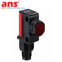
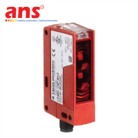
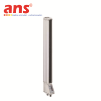
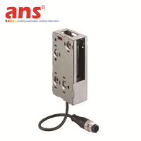
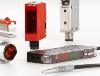
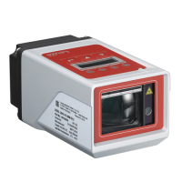
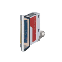
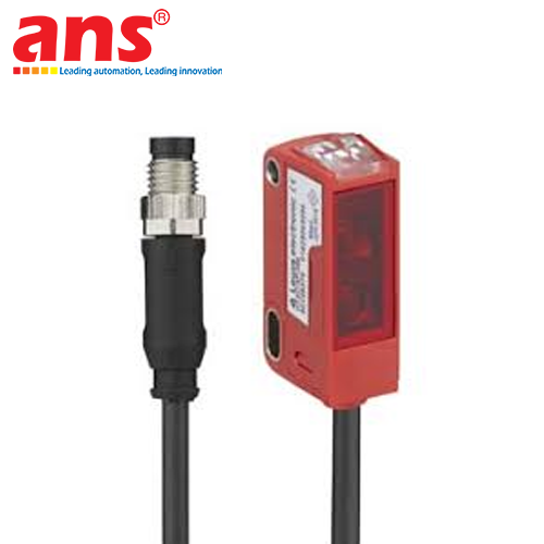
Product Overview: The Leuze LE3C/4W-200-M8 throughbeam photoelectric sensor receiver is a high-performance sub-miniature object diagnostics instrument belonging to the world-renowned space-saving Series 3C portfolio, engineered and manufactured by Leuze in Germany. Within modern smart commercial spaces, hyper-scale conveyor setups, vertical form-fill-seal packaging units, and automated electronic micro-component assembly systems, executing non-contact target tracking within extremely small, tight mechanical boundaries demands terminal equipment that features heavily stripped-down outer dimensions while retaining long-range optical performance parameters.
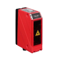
The LE3C/4W-200-M8 configuration meets these intricate parameters directly, operating exclusively as the high-fidelity Receiver module which pairs seamlessly with a matching Series 3C Leuze transmitter to construct a rugged throughbeam baseline sensing loop that remains uncompromised by target material variance, optimizing 24/7 continuous industrial processing loops.
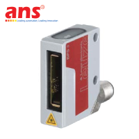
Absolute Surface Finish Autonomy and Extended Throughbeam Dynamic Range: The underlying technological paradigm driving the LE3C/4W-200-M8 variant leverages sophisticated Throughbeam light obstruction physics. The matching system transmitter continuously projects an uninterrupted optical beam directly across an open factory lane toward the receiver lens of the LE3C/4W-200-M8 unit mounted parallel opposite. In the standard unobstructed baseline state, the receiver captures full optical energy input, keeping internal data gates secure. The moment an oncoming medium (such as a cardboard box shell, manufacturing component, container package, or clear polymer film) steps into the spatial cross-section between the dual hardware blocks, the light path vector is broken, routing an instantaneous status change straight to the output switching stage.
Because the emitting and receiving hardware are housed inside separate isolated frameworks, the sensor achieves a spectacular guaranteed operating range spanning from 0 to 15 meters. The primary physical asset of this throughbeam layout is its complete autonomy over target material contrast variances, specular glare, matte black texturing, or high-gloss polymer surfaces, maintaining absolute tracking fidelity and cutting through heavy atmospheric facility dust layers or vapor mists easily.
Adaptive Push-Pull Telemetry Configuration and Sub-miniature Geometry:
-
Universal Self-Adapting Push-Pull Stage (Code 4W): The hallmark mechatronic differentiator of the LE3C/4W-200-M8 build iteration centers on its advanced Push-Pull switching output technology. This solid-state architecture equips a single physical output port with the capability to automatically match separate control loop topologies: functioning as a positive current sourcing PNP output or operating as a negative common sinking NPN output simultaneously. This eliminates the requirement to order separate PNP and NPN part variants for specific facility electrical panels, interfacing effortlessly with all industrial PLC brands and minimizing spare hardware stock investments. The output wire can be set for Light ON or Dark ON logic paths via a dedicated remote electronic Teach input line.
-
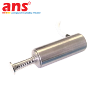
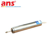
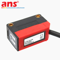
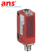
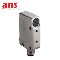
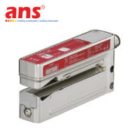
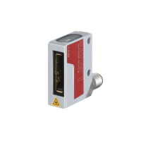
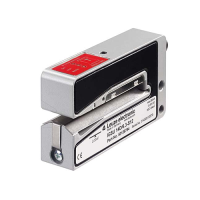
Sub-miniature Footprint for Intricate Mechanical Integration: The receiver shell profiles a highly optimized physical block showing a width of 15 mm, a height of 32 mm, and a length of 20 mm, with a net mass of exactly 20 grams. This miniature setup empowers mechanical design crews to plant the device deep inside structural tool slots, mechanical joints, or small automated machine chases where conventional industrial M18 sensors cannot be deployed.
🛠️ FIELD INSTALLATION PROMPT & TERMINAL WIRING TOPOLOGY:
-
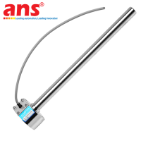
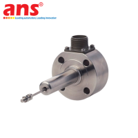
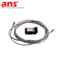
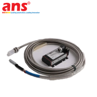
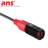
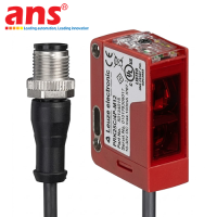
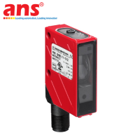
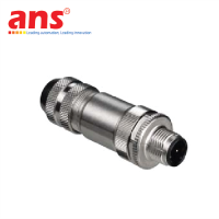
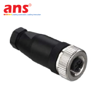
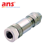
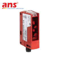
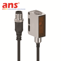
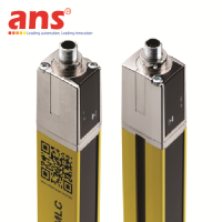
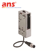
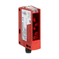
High-Flex Pigtail Cable with Standard M8 Male Coupling: Electrical interface routing utilizes a pre-wired, high-flex 200 mm pigtail extension cable terminated with an A-coded, M8, 4-pin male socket link. This layout deflects mechanical bending stresses on the housing joint when tracking on dynamic automated components, maximizing structural wire lifecycle parameters.
-
Standardized Conductor Pin Allocation Map: The industrial connectivity standard is mapped as follows:
-
Pin 1 (Brown wire): Routes positive 10 to 30 VDC driving utility power.
-
Pin 3 (Blue wire): Routes negative 0 V common line loop.
-
Pin 4 (Black wire): Routes real-time discrete telemetry from the Push-Pull transistor gate.
-
Pin 2 (Trắng wire): Connects remote electronic configuration line for sensitivity calibration adjustments.
-
Severe-Duty Material Hardening and Performance Metrics: To isolate internal calculation circuits and receiving optical diodes from aggressive industrial workspace vibration forces, the sensor internals are encased inside a high-density industrial PC-ABS polymer composite shell paired with a scratch-resistant PMMA Acrylic lens assembly. Certified to international IP67 environmental ingress protective indices, it provides a dust-tight barrier impervious to water splashes or facility condensation, operating with absolute consistency over an extended thermal window scaling from minus 40 up to plus 60 degrees Celsius (ideal for industrial sub-zero cold-storage networks). Resolving process changes with an ultra-fast response speed of precisely 1 ms (matching an electronic switching pulse frequency of 500 Hz), the sub-miniature device tracks high-density product currents smoothly without data dropouts.
| Engineering Metric | Technical Value and Standard (Plain-Text Compliant) |
| Manufacturer | Leuze Electronic (Germany) |
| Product Series | Series 3C Sub-miniature Compact Photoelectric Portfolio |
| Functional Configuration | Receiver Module (Sensing block of an independent throughbeam system) |
| Model Designation | LE3C/4W-200-M8 |
| Order Identification Code | 50147147 |
| Measurement Principle | Light obstruction physics using separate Throughbeam technology |
| Guaranteed Operating Range | From 0 up to 15 meters distance window bounds (Requires matching 3C Transmitter) |
| Driving Utility Power | 10 to 30 VDC nominal input tolerance, running across smooth industrial DC grids |
| No-Load Current Consumption | Ultra-efficient electrical design drawing less than or equal to 20 mA |
| Control Signal Architecture | 1 x Universal Solid-State Digital Output driven via high-performance Push-Pull stage |
| Operating Output Topology | Light ON or Dark ON field-selectable modes (Configured via remote Teach link) |
| Signal Response Latency | Ultra-fast data processing tracking inside a 1 ms window mượt mà |
| Switching Pulse Frequency | Electronic closing rate locked at a stable 500 Hz frequency (500 cycles per second) |
| System Turn-On Initialization | Ready Delay processing time locked within a 300 ms envelope |
| Electrical Interface Footprint | Pre-wired 200 mm high-flex Pigtail Cable with integrated M8 Male 4-pin Connector |
| Pin Alignment and Coding | 4-pin arrangement complying with A-coded industrial connectivity standards |
| Physical Housing Compound | Premium high-density industrial PC-ABS polymer resin structural casing |
| Optical Lens Composition | High-clarity scratch-resistant impact-resistant PMMA Acrylic Lens assembly |
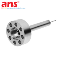
| Mechanical Mounting Profile | Through-hole direct pass-through mounting hole configuration |
| Enclosure Environmental Ingress | Certified to international IP67 protection ratings (Dust-proof and spray immune) |
| Process Temperature Boundaries | Handles severe facility thermal fields scaling from minus 40 up to plus 60 degrees Celsius |
| Physical Housing Dimensions | Width 11 mm x Height 32 mm x Length 20 mm (Sub-miniature footprint link) |
| Total Hardware Net Mass | Ultra-lightweight robotic footprint weighing exactly 20 grams |
| Circuit Safety Protection | Integrated reverse polarity protection barrier and output short-circuit containment |
| Country of Origin | 100% Manufactured, assembled, and calibrated in Germany |