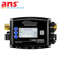
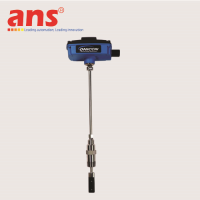
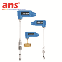
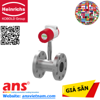
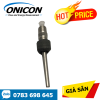
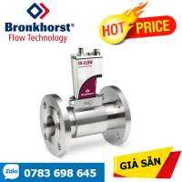
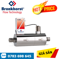
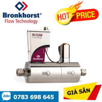
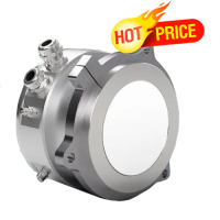
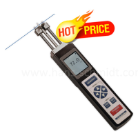
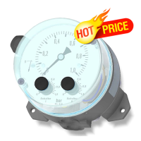
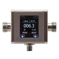
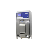
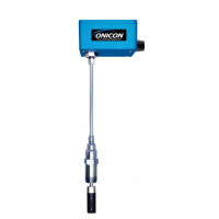
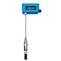
ONICON FT-4600-341-000-09 3/4 Inch High Flow Inline Ultrasonic Flow Meter
Price: Contact
Brand: ONICON
Category: Thiết bị đo lường & Kiểm tra
Supplier: AnhNghiSon
Origin: USA
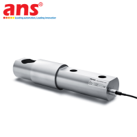
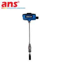
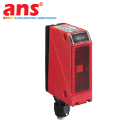
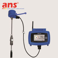
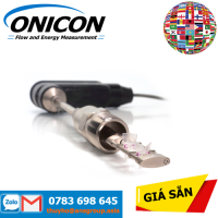
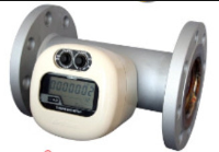
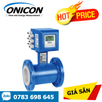
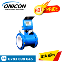
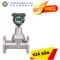
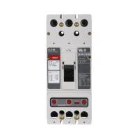
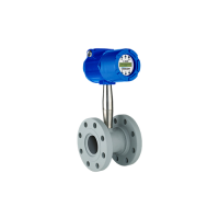
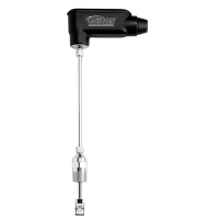
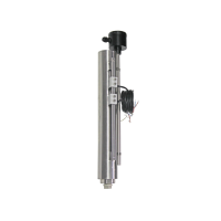
ONICON FT-4600-341-000-09
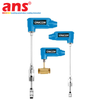
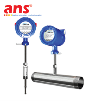
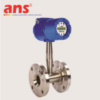
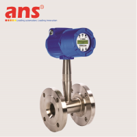
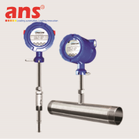
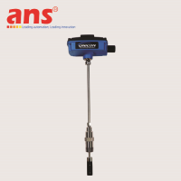
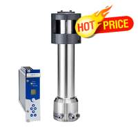
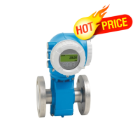
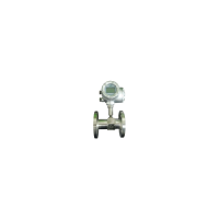
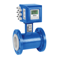
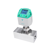
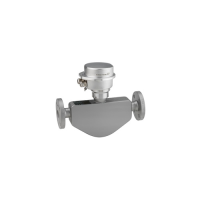
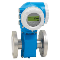
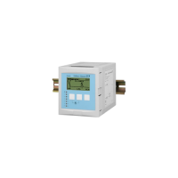
Product Overview: The ONICON FT-4600-341-000-09 Inline Ultrasonic Flow Meter is a specialized process-grade high-capacity fluid diagnostics instrument belonging to the world-renowned FT-4600 Series portfolio, engineered and manufactured 100% in the United States (USA Origin) by ONICON Incorporated. Within advanced mechanical infrastructures of smart commercial systems, hyper-scale Data Center cooling topologies, high-output industrial automation loops, and heavy HVAC plants, executing rigorous, uncompromised flow telemetry along small-diameter 3/4-inch (DN20) pipe branches experiencing accelerated volumetric velocity and high dynamic thrust is a substantial engineering challenge.
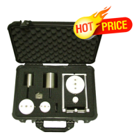
The FT-4600-341-000-09 variation profiles a completely solid-state structural design that eliminates internal mechanical moving components like turbines or rotors, avoiding mechanical wear and friction decay while preserving absolute long-term measurement fidelity over decades of industrial runtimes. Every individual unit is fully factory-configured and wet-calibrated on precision laboratory flow loops prior to dispatch, shipping in a plug-and-play state that allows immediate operational runtime right out of the box once mechanical plumbing couplings and gaskets are locked down.
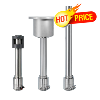
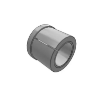
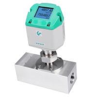
High-Flow Volumetric Design Optimization: The defining engineering attribute of this specific hardware configuration centers on the specialized chamber model designation 341 (3/4" High Flow). ONICON splits its 3/4-inch (DN20) product matrix into two distinctive dynamic classifications: the 340 model family optimized for standard flow profiles, and the 341 model variant tailored for high-velocity streams. The 341 pipeline footprint features a structurally optimized internal hydro-path that accommodates massive flow accelerations without generating acoustic wave saturation, cavitation signal clipping, or phase distortion. This ensures supreme accuracy under intense dynamic pressure loads and extends mechanical lifecycle performance in high-demand hydronic industrial infrastructure loops.
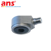
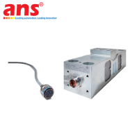
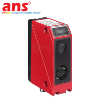
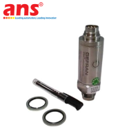
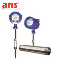
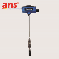
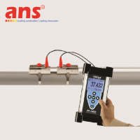
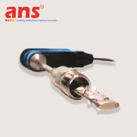
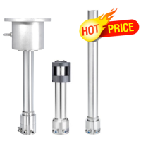
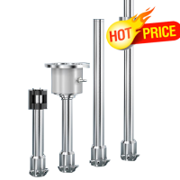
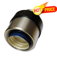
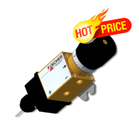
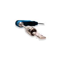
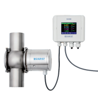
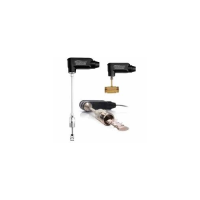
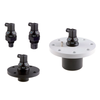
Differential Transit-Time Engineering and Wetted Sensor Technology: The underlying technological paradigm driving the FT-4600-341-000-09 variant leverages sophisticated Differential Transit-Time Ultrasonic physics. The defining hardware asset of this specific model is its native incorporation of high-precision acoustic sensors that submerge directly into the active flow loop (Wetted Ultrasonic Transducers). These high-fidelity sensing nodes are forged from an advanced 40% glass-fiber reinforced PPS (Polyphenylene Sulfide) technical composite, providing superb resilience against fluid friction and chemical cavitation breakdown.
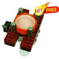
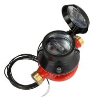
The two acoustic transducers are mounted directly opposite each other across a linear transmission line vector inside the non-corrosive Lead-Free Brass flow body channel. As the processed medium (water or industrial water/glycol solutions) glides through the tube, the digital telemetry engine shoots alternating high-frequency acoustic wave pulses upstream and downstream relative to the flow direction vector. The internal calculation processor analyzes the microscopic time-of-flight delta between these sonic signals to resolve continuous process velocity with exceptional data resolution. This direct-path wetted layout (Direct Beam Path) optimizes soundwave signal strength, delivers supreme operational consistency over multi-year runtime windows, and unlocks superior low-velocity flow tracking metrics. Because the inner measuring aperture is completely open, smooth, and unobstructed, it introduces zero physical restriction to the fluid stream, ensuring optimal pipeline pressure retention and decreasing utility pumping workloads.
🛠️ FIELD INSTALLATION PROMPT & HYDRAULIC CONFIGURATION:
-
Strict Straight Pipe Run Metrics: To preserve the factory-certified accuracy threshold of plus or minus 1% of active reading, mechanical installers deploying this 3/4-inch inline device must strictly maintain specified minimum straight pipe runs upstream and downstream from adjacent pipe fittings to secure a completely laminar velocity profile:
-
Downstream of a Single Elbow: Requires 0D of straight pipeline run.
-
Downstream of a mechanical Reducer fitting: Requires 0D of straight pipeline run.
-
Downstream of a Hydronic Heating/Cooling Coil loop: Requires a minimum of 3D straight pipe run.
-
Downstream of a mechanical Isolation Valve: Requires a minimum of 3D straight pipe run.
-
Downstream of an automated modulating Control Valve: Requires a minimum of 10D straight pipe run.
-
-
Field System Commissioning Rules: To safeguard wetted sensors and verify telemetry accuracy, the target pipeline loop must remain filled with liquid medium at all times, with the flow aligned to the structural arrow embossed on the brass casing. Flushing the system piping grid to remove abrasive metallic debris or loose welding scales prior to mechanical mounting is strongly mandated.
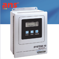
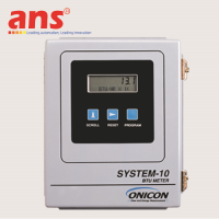
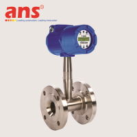
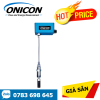
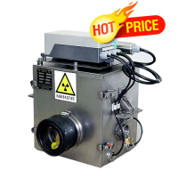
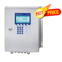
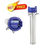
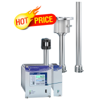
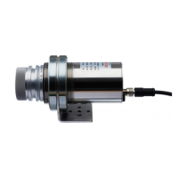
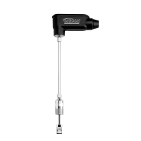
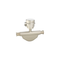
Hardened Electronic Transmitter Shell with 1/2" NPT Conduit Adapter Connection:
-
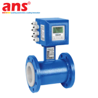
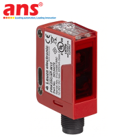
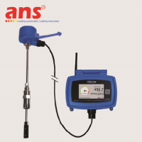
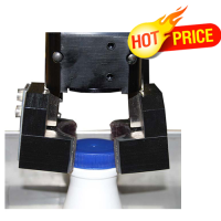
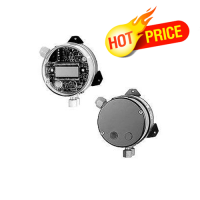
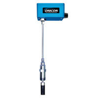
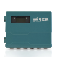
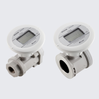
Conduit-Protected Blind Enclosure Layout (Code 000): Shifting away from 020 configurations featuring flexible compression rubber glands (Cord Grips), the 000 build model incorporates a rugged industrial NEMA 4 housing integrated with a physical 1/2-inch NPT Conduit Adapter. This mechanical hub layout empowers field electrical crews to thread rigid steel or flexible liquid-tight protective conduits straight into the wiring terminal box of the flow meter. This architectural layout provides maximum physical wire shielding, deflecting mechanical impact shears, preventing rodent damage on field lines, and completely isolating internal calculator microchips from extreme environmental moisture or condensation sweating common to cold chilled water lines. This blind transmitter layout drops the localized LCD panel and fieldbus cards (No BACnet MS/TP, no Modbus RTU), utilizing an intuitive onboard LED diagnostic block instead.
-
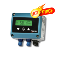
Synchronized Dual Output Matrix: Features concurrent real-time data loops via an Analog channel and a discrete Pulse channel. The Analog Output is fully field-configurable, allowing automation crews to match supervisory PLC or SCADA loops using standard current or voltage loops including 4–20 mA, 0–10 VDC, or 0–5 VDC spans. The Pulse Output channel utilizes an isolated solid-state Dry Contact Pulse topology. Acting as an isolated mechanical-free electronic switch, it relays high-fidelity tracking data straight to remote totalizer units or BMS logging panels while repelling dangerous electrical line noise or high-frequency EMI generated by neighboring variable frequency drives (VFDs).
-
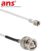
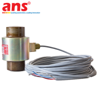
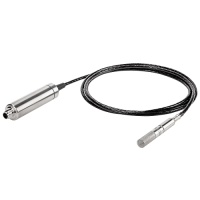
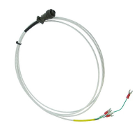
Pre-Supplied Cable Harness: The meter includes a pre-wired 10 ft (approximately 3 meters) cable harness sorting utility power lines, analog loops, and pulse circuits. For extended panel runs, the manufacturer recommends deploying premium 18 to 22 AWG shielded instrumentation cabling to prevent data degeneration from adjacent heavy EMI fields.
| Engineering Metric | Technical Value and Standard (Plain-Text Compliant) |
| Manufacturer | ONICON Incorporated (United States) |
| Product Series | FT-4600 Series Inline Ultrasonic Fluid Instrumentation Portfolio |
| Full Manufacturing Code | FT-4600-341-000-09 |
| Measurement Principle | Non-intrusive Non-mechanical Differential Transit Time Ultrasonic physics |
| Dynamic Configuration | Optimized High Capacity Dynamic Path (3/4" High Flow Build / Differentiated from 340 standard line) |
| Nominal Pipe Dimension | 3/4 Inch / Metric Designation DN20 High Flow |
| Mechanical Interface | Standard Industrial NPT Threaded connection utilizing matching couplings and gaskets |
| Transmitter Interface Enclosure | Blind execution containing no local display panel; configured with a 1/2" NPT Conduit Adapter |
| Onboard Diagnostics Display | Integrated LED status check block tracking electronic health metrics |
| System Accuracy Standard | Plus or minus 1% of active reading across standard flow velocities (1% Reading) |
| Measurement Repeatability | Extremely stable tracking consistency, always plus or minus 0.2% |
| Overall Dynamic Range | Spectacular Turndown Ratio locked at 500:1 |
| Maximum Line Pressure | Heavy-duty 400 psi structural pressure envelope (Approximately 27.6 bar) |
| Process Temperature Boundaries | Handles fluid media thermal windows spanning minus 18 to 121 degrees Celsius |
| Ambient Temperature Envelope | Operates flawlessly from minus 25 to 55 degrees Celsius |
| Driving Utility Power | 24 VAC/DC nominal input tolerance, running across 20 to 28 VAC/DC utility bounds |
| Maximum System Power Load | Highly efficient electrical design consuming less than or equal to 5 VA Max |
| Analog Output Channel | 1 x Field-Configurable Analog Loop (Selectable for 4–20 mA / 0–10 VDC / 0–5 VDC) |
| Discrete Output Channel | 1 x Isolated Dry Contact Pulse Output (Optimized for remote totalizer / PLC logging / BMS systems) |
| Fieldbus Communications | Default variation comes naked with no onboard BACnet MS/TP or Modbus RTU cards |
| Flow Body Metallurgy | Forged entirely from high-grade industrial Lead-Free Brass alloy |
| Transducer Structural Material | Polyphenylene Sulfide (PPS) engineered resin reinforced with 40% glass fiber |
| Enclosure Environmental Rating | Certified to NEMA 4 industrial protective standards |
| Field Maintenance Requirement | Zero mechanical maintenance overhead due to a solid-state design containing absolutely no moving components |
| Country of Origin | 100% Made in the United States |